some ADEs that organizes examples into categories and allows you to easily browse and
search installed examples. You can see descriptions and compatible hardware models for each
example or see all the examples compatible with one particular hardware model.
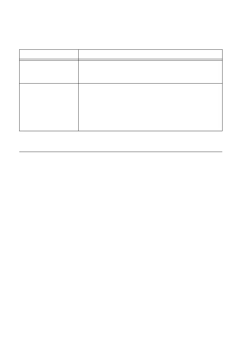
Table 8. Locating NI-RFSA Examples
ADE How to Locate Examples
LabVIEW or
LabWindows/CVI
Locate examples with the NI Example Finder. Within LabVIEW
or LabWindows/CVI, select Help»Find Examples and navigate
to Hardware Input and Output»Modular Instruments.
ANSI C or Microsoft
Visual C/C++
Locate examples in the <NIDocDir>\NI-RFSA\examples
directory, where <NIDocDir> is one of the following directories:
• Windows 8/7/Vista—Users\Public\Public
Documents\National Instruments
• Windows XP—Documents and Settings\All
Users\Documents\National Instruments
Troubleshooting
If an issue persists after you complete a troubleshooting procedure, contact NI technical
support or visit ni.com/support.
Installation
What Should I Do if the NI 5600 RF Downconverter Module
Front Panel POWER LED is Off When the PXI Chassis is On?
If the POWER LED fails to light after you power on the PXI chassis, a problem may exist
with the PXI power rail, a hardware module, or the LED.
1. Disconnect any signals from the PXI module front panel.
2. Power off the PXI chassis.
3. Remove the module from the PXI chassis and inspect it for damage. Do not reinstall a
damaged device.
4. Reinstall the module in a different PXI chassis slot.
5. Power on the PXI chassis.
6. Verify that the device appears in MAX.
7. Reset the device in MAX and perform a self-test.
Why Is the ACCESS LED Off When the Chassis is On?
The LEDs may not light until the device has been configured in MAX. Before proceeding,
verify that the NI 5661 appears in MAX.
If the ACCESS LED fails to light after you power on the chassis, a problem may exist with the
chassis power rails, a hardware module, or the LED.
18
| ni.com | NI PXI-5661 Getting Started Guide

 Loading...


