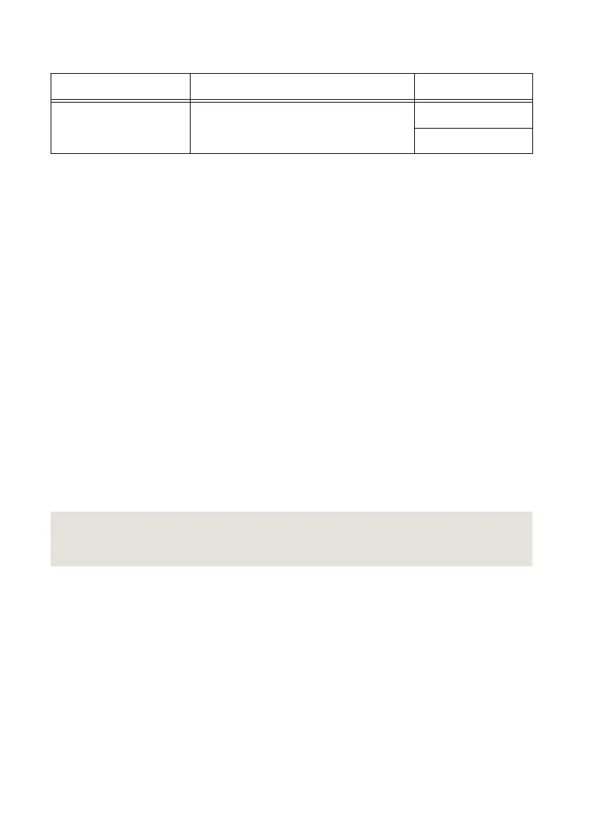
Table 9. Voltage Output and Measurement Adjustment
Level Range Limit Range and Limit Test Point
10 V 6 A 0.1 V
10 V
1. Set the first specified level range, limit range, and limit on the NI 4113.
2. Set the level on the NI 4113 to the first specified test point.
3. Take a voltage measurement using the DMM, and take a voltage measurement using the
NI 4113.
4. Store the values from the previous step as inputs for the niDCPower Cal Adjust VI or
function called in the following steps.
5. Repeat the previous three steps for each test point specified in the level range.
6. Update the measurement calibration constants by configuring and calling the niDCPower
Cal Adjust Voltage Measurement VI or
niDCPower_CalAdjustVoltageMeasurement function.
a) Input the DMM measurements as the measured outputs.
b) Input the NI 4113 measurements as the reported outputs.
c) Input the specified level range as the range.
7. Update the output calibration constants by configuring and calling the niDCPower Cal
Adjust Voltage Level VI or niDCPower_CalAdjustVoltageLevel function.
a) Input the DMM measurements as the measured outputs.
b) Input the test points as the requested outputs.
c) Input the specified level range as the range.
8. If more than one level range is specified, repeat the previous steps using the values
specified in each level range.
Related Information
For information about VIs or functions, refer to the programming reference of the NI DC
Power Supplies and SMUs Help.
Connecting and Configuring Equipment for Current
Adjustment
1. Make the necessary connections for this procedure, as shown in the following figure.
NI PXIe-4113 Calibration Procedure | © National Instruments | 15

 Loading...
