■
Green ON steady—PXI and onboard power is on and within regulation
limits.
■
Green BLINKING—The controller has entered the so o state and is safe
to power down.
Note This status is applicable only when the chassis is set to
Manual Inhibit Mode.
■
Green FADING—The controller has entered the sleep (S3) state.
■
OFF—The controller is powered o.
■
Red BLINKING—The controller detected a power rail fault when trying to
boot.
■
Red SOLID—The controller detected a thermal fault and has shut down to
protect the system.
■
USER LEDs — Two bi-color green/yellow LEDs (USER1 and USER2) that you
can define to meet the needs of your LabVIEW application.
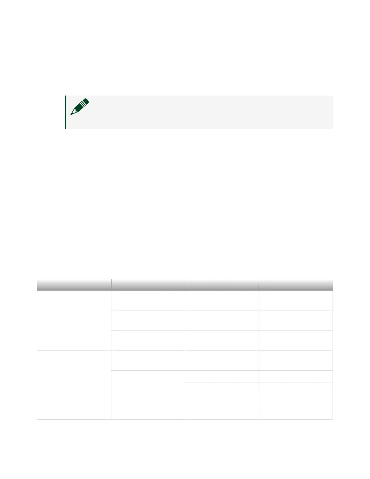
The following table lists and describes the 10M/100M/1000M/2.5G LAN connector
LED states.
Table 1. 10M/100M/1000M/2.5G LAN Connector LED States
LED Color LED State Condition
2.5G
1000
10/100
Green On 2.5 Gb/s data rate is
selected
Amber On 1000 Mb/s data rate is
selected
Unlit O 10/100 Mb/s data rate
is selected
ACT/LINK Unlit O LAN link is not
established
Green On (steady state) LAN link is established
On (pulsing) The controller is
communicating with
another device on the
LAN
© National Instruments
11
PXIe-8822/42/62 Getting Started
 Loading...