© National Instruments Corporation 17 NI sbRIO-961x/9612XT/963x/9632XT/964x/9642XT
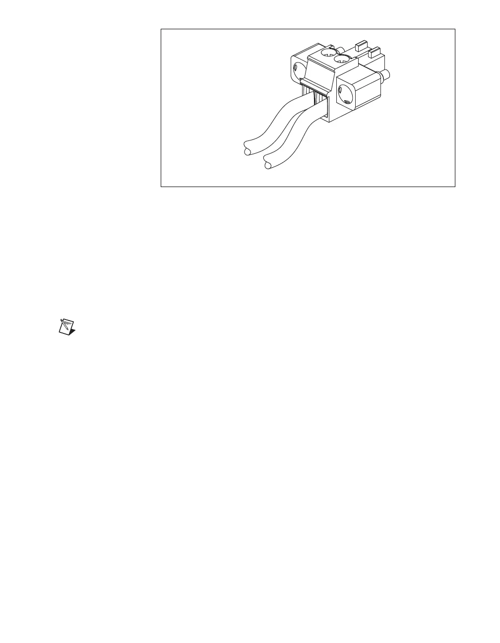
Figure 13. Connecting a Power Supply
1. Remove the MINI-COMBICON plug from connector J3 of the
NI sbRIO device. Refer to Figure 4 for the location of J3.
2. Connect the positive lead of the power supply to the V terminal of the
MINI-COMBICON plug.
3. Connect the negative lead of the power supply to the C terminal of the
MINI-COMBICON plug.
4. Re-install the MINI-COMBICON connector in connector J3.
Note The 24 V digital output of the NI sbRIO-964x/9642XT requires a separate,
additional power supply. Refer to the Integrated 24 V Digital Output
(NI sbRIO-964x/9642XT Only) and Specifications sections for more information about
powering digital output channels.
Powering On the NI sbRIO Device
When you apply power to the NI sbRIO device, the device runs a power-on
self test (POST). During the POST, the Power and Status LEDs turn on.
When the Status LED turns off, the POST is complete. If the LEDs do not
behave in this way when the system powers on, refer to the Understanding
LED Indications section.
You can configure the device to launch an embedded stand-alone
LabVIEW RT application each time it is booted. Refer to the Running a
Stand-Alone Real-Time Application (RT Module) topic of the LabVIEW
Help for more information.
 Loading...