NI sbRIO-961x/9612XT/963x/9632XT/964x/9642XT 6 ni.com
I/O and Other Connectors on the NI sbRIO Device
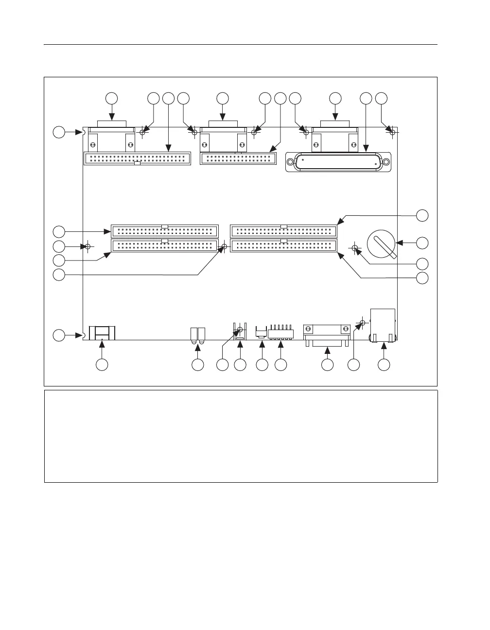
Figure 4 shows the locations of parts on the NI sbRIO device.
Figure 4. NI sbRIO Device Parts Locator Diagram
1 J10, Connector for C Series Module 3
2Plated Mounting Holes
3 J7, Analog I/O Connector
4 J9, Connector for C Series Module 2
5 J6, 24 V Digital Input (sbRIO-964x/9642XT Only)
6J8, Connector for C Series Module 1
7 J5, 24 V Digital Output (sbRIO-964x/9642XT Only)
8 P4, 3.3 V Digital I/O
9Backup Battery
10 P2, 3.3 V Digital I/O
11 J2, RJ-45 Ethernet Port
12 J1, RS-232 Serial Port
13 DIP Switches
14 Reset Button
15 P1, Ground Lug
16 LEDs
17 J3, Power Connector
18 P3, 3.3 V Digital I/O
19 P5, 3.3 V Digital I/O
17
16
11
10
13
1415
9
19
6
8
12
4
1
3 722 2 2 2
2
2
2
2
2
2
2
18
5
 Loading...