© National Instruments Corporation 7 SCB-68 User Guide
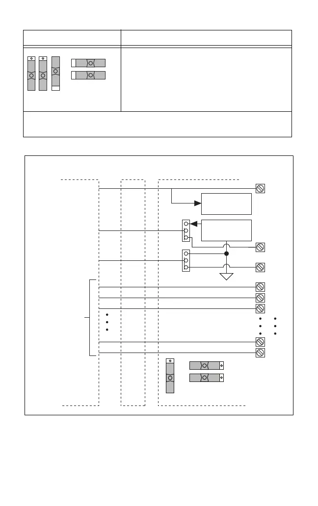
Figure 4. MIO DAQ Device Modes Switch Settings
Direct feedthrough mode—Move switches S1, S2,
S3, S4, and S5 to the positions shown at left. In this
mode:
• All 68 signals from the device connect directly to
screw terminals.
Refer to Figure 3 for a detailed diagram.
*
Not available on Connector 1 of NI 6225/6255 devices.
†
Not available on S Series devices.
Table 2. MIO DAQ Device Switch Settings (Continued)
Switch Setting Description
S5 S4 S3
S1
S2
Te m p e rature
Sensor
MIO DAQ Device Cable SCB-68
S5
S4
Screw
Terminal
67
66
3
2
1
34
8
68
67
66
3
2
1
34
8
68
S3
S1
S2
+5 V
AI 0
AI 8
Other
Pins
Refer to
Yo ur Device
Documentation
for Device
Signal
Information
Signal
Conditioning
 Loading...


