Do you have a question about the National Instruments SCB-68 and is the answer not in the manual?
Describes text conventions used in the manual for clarity and consistency.
Lists resources for more information on using the SCB-68 with DAQ devices.
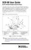
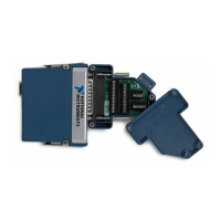
Lists necessary items to set up and use the SCB-68 connector block.
Details compatible DAQ devices and cabling options for the SCB-68.
Explains SCB-68 configuration in MAX and provides critical safety information.
Provides step-by-step instructions for connecting signals to the SCB-68.
Details the five switches on the SCB-68 and their impact on signal types.
Explains connecting analog input signals for single-ended or differential input modes.
Describes NRSE, RSE, and DIFF input modes for analog signals.
Details connections for nonreferenced/floating and ground-referenced signal sources.
Covers connecting digital signals and timing signals to the SCB-68.
Provides recommendations for minimizing noise pickup and maximizing measurement accuracy.
Explains how to configure switches for thermocouple measurements and cold-junction compensation.
Discusses high-value resistors and lowpass filters for thermocouple measurements.
Explains using component pads to condition analog input channels.
Details conditioning for analog output channels and PFI0/TRIG1.
Covers maximizing measurement accuracy by considering code width, gain, and resolution.
Describes circuitry for detecting open or defective thermocouples.
Explains lowpass filtering for noise and antialiasing applications.
Details adding components to measure current using Ohm's Law.
Explains using voltage dividers to attenuate signals exceeding DAQ device input limits.
Lists specifications for analog input channels, temperature sensor, and power requirements.
Covers physical dimensions, maximum working voltage, and environmental operating conditions.
Details safety standards, electromagnetic compatibility, and CE compliance requirements.
Shows pinouts for E Series, 670X, 671X/673X, S Series, 660X, 653X, and 7811R/7831R devices.
Explains the 800 mA fuse protecting the +5 V line and resistor filtering.
Illustrates circuit diagrams for +5 V power, cold-junction compensation, digital trigger, and analog output.
Provides instructions for soldering and desoldering components on the SCB-68 printed circuit board.
Guides users to online support, training, and system integration services.
Provides information on obtaining calibration certificates for NI products.
Provides definitions for prefixes, numbers, symbols, and technical terms used in the manual.
An index to help locate specific topics within the manual.
| Storage Temperature Range | -20 °C to 70 °C |
|---|---|
| I/O Channels | 68 |
| Shielded | Yes |
| Terminal Type | Screw Terminal |
| Operating Temperature Range | 0 °C to 50 °C |
| Compatibility | National Instruments DAQ devices |
| Cable Length | Not applicable |