Chapter 3 Connecting Signals
SCB-68 Shielded Connector Block User Manual 3-12 ni.com
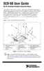
Figure 3-7. Digital I/O Connections
Connecting Timing Signals
If you are using a 68-pin or 100-pin DAQ device, all external control over
device timing is routed through the programmable function input (PFI)
lines <0..9>. These PFI lines are bidirectional; as outputs they are not
programmable and reflect the state of many DAQ, waveform generation,
and general-purpose timing signals. The remaining timing signals use
five different dedicated outputs.
Note For more information, refer to the device user manual at ni.com/manuals for
detailed signal description and connection information.
+5 V
LED
TTL Signal
+5 V
Switch
I/O Connector
DGND
SCB-68
DIO<0..3>
DIO<4..7>
 Loading...