Chapter 5 Adding Components for Special Functions
SCB-68 Shielded Connector Block User Manual 5-20 ni.com
Selecting Components
To set up the resistors, complete the following steps:
1. Select the value for R
2
(10 kΩ is recommended).
2. Use Equation 5-12 to calculate the value for R
1
. Base the R
1
calculation
on the following values:
• Maximum V
in
you expect from the transducer
• Maximum voltage (<10 V
DC
) that you want to input to the DAQ
device
Accuracy Considerations
For best results when attenuating voltage, you should choose a resistor that
has the following characteristics:
• Low wattage of approximately 1/8 W
• Precision of at least 5%
• Temperature stable
• Tolerance of 5%
• AXL package (suggested)
• Carbon or metal film (suggested)
Verify t h a t R
1
and R
2
drift together with respect to temperature; otherwise,
the system may consistently read incorrect values.
Adding Components
You an build a two- or three-resistor circuit for attenuating voltages at the
single-ended inputs, differential inputs, analog outputs, and digital inputs
of the SCB-68.
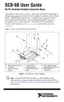
Single-Ended Input Attenuators
To build a two-resistor circuit for attenuating voltages at the single-ended
inputs of the SCB-68, refer to Figure 5-20.

 Loading...