Chapter 5 Adding Components for Special Functions
SCB-68 Shielded Connector Block User Manual 5-22 ni.com
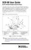
Analog Output and Digital Input Attenuators
To build a two-resistor circuit for attenuating voltages at the DAC0OUT,
DAC1OUT, and TRIG1 pins on the SCB-68, refer to the pad positions in
Figure 5-22.
Figure 5-22. SCB-68 Circuit Diagram for Digital Input Attenuation
Use positions R1 and RC1 for TRIG1, and determine the gain according to
Equation 5-17:
(5-17)
Use positions R2 and RC2 for DAC1OUT, and determine the gain
according to Equation 5-18:
(5-18)
Use positions R3 and RC3 for DAC0OUT, and determine the gain
according to Equation 5-19:
(5-19)
Special Considerations for Analog Input
When calculating the values for R
1
and R
2
, consider the input impedance
value from the point of view of V
in
, as Figure 5-23 shows.
C
F
R
E
V
in
V
m
ACH<
i
>
ACH<
i
+8>
+
–
+
–
G
RC1
RC1 R1+()
-----------------------------=
G
RC2
RC2 R2+()
-----------------------------=
G
RC3
RC3 R3+()
-----------------------------=

 Loading...