Chapter 5 Adding Components for Special Functions
SCB-68 Shielded Connector Block User Manual 5-4 ni.com
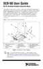
Figure 5-3. Analog Output Channel Configuration Diagram for DAC0OUT
Conditioning PFI0/TRIG1
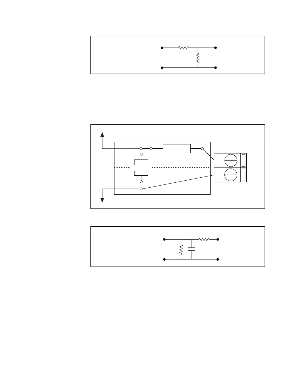
Figure 5-4 illustrates the digital input channel configuration, and
Figure 5-5 shows the digital input channel configuration for PFI0/TRIG1.
Figure 5-4. Digital Input Channel Configuration Diagram
Figure 5-5. Digital Input Channel Configuration Diagram for PFI0/TRIG1
RC3
AOGND
C
DAC0OUT
R3
+
–
PFI0/TRIG1
DGND
(R1)
11
44
(RC1)
RC1
DGND
C
PFI0/TRIG1
R0
+
–
 Loading...