Chapter 5 Adding Components for Special Functions
SCB-68 Shielded Connector Block User Manual 5-16 ni.com
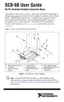
Apply a lowpass filter to the signal to remove the high-frequency
component for a cleaner digital signal, as Figure 5-17 shows.
Figure 5-17. Lowpass Filtering of Digital Trigger Input Signals
Note
Due to the filter order, the digital trigger input signal is delayed for a specific amount
of time before the DAQ device senses the signal at the trigger input.
Measuring a 4 to 20 mA Current
Since DAQ devices cannot directly measure current, this section describes
how to add components for measuring current when transistors output a
current value ranging between 4 and 20 mA.
Theory of Operation
The conversion from current to voltage is based on Ohm’s Law, which is
summarized by Equation 5-7, where V is voltage, I is current and R is
resistance:
(5-7)
Thus, you must multiply current by a constant to convert the current to a
voltage. In an electrical circuit, current must flow through a resistor to
produce a voltage drop. This voltage drop then becomes the input for a
DAQ device, as Figure 5-18 shows.
Time (t)
Volts (V)
VIR×=
 Loading...