SCB-68 User Guide 6 ni.com
Using the SCB-68 with MIO DAQ Devices
You can take measurements with the SCB-68 and multifunction I/O (MIO)
DAQ devices, such as E/M/S Series devices, in a number of ways. Switches
S1 and S2 provide power to the signal conditioning area of the accessory.
The SCB-68 has a temperature sensor for cold-junction compensation (CJC)
to accommodate thermocouples; switches S3, S4, and S5 configure the
temperature sensor for different analog input settings. Table 2 shows the
different switch settings for MIO DAQ devices.
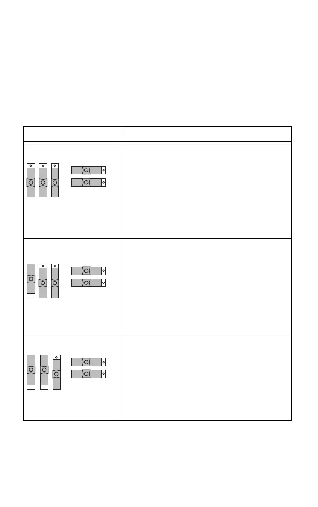
Table 2. MIO DAQ Device Switch Settings
Switch Setting Description
MIO with disabled temperature sensor mode
(default configuration)
*
—Move switches S1, S2,
S3, S4, and S5 to the positions shown at left. In this
mode:
• The temperature sensor is not used.
• AI 0 and AI 8 are available on screw terminals.
• +5 V power provided to signal conditioning area of
the accessory.
Refer to Figure 4 for a detailed diagram.
MIO with single-ended temperature sensor
mode
*,†
—Move switches S1, S2, S3, S4, and S5 to
the positions shown at left. In this mode:
• The temperature sensor can be read using AI 0 in
referenced single-ended (RSE) mode.
• AI 8 is available on a screw terminal.
• +5 V power provided to signal conditioning area of
the accessory.
Refer to Figure 4 for a detailed diagram.
MIO with differential temperature sensor
mode
*
—Move switches S1, S2, S3, S4, and S5 to
the positions shown at left. In this mode:
• The temperature sensor can be read using AI 0 and
AI 8 in differential mode.
• +5 V power provided to signal conditioning area of
the accessory.
Refer to Figure 4 for a detailed diagram.
S5 S4 S3
S1
S2
S5 S4 S3
S1
S2
S5 S4 S3
S1
S2
 Loading...


