Table 11. NI USRP-2922 Module LEDs (Continued)
LED Indication
E Indicates the reference lock status of the LO on the module:
OFF—There is no reference signal, or the LO is not locked to a reference signal.
BLINKING—The LO is not locked to a reference signal.
GREEN—The LO is locked to a reference signal.
F Indicates the power status of the module:
OFF—The module is powered off.
GREEN—The module is powered on.
NI USRP-2930
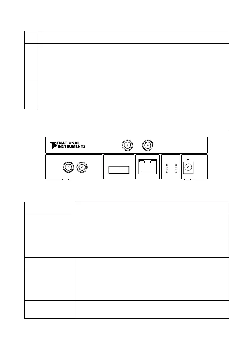
Figure 10. NI USRP-2930 Front Panel
MIMO EXPANSION GB ETHERNET
RX 1
TX 1
REF IN PPS IN
A
C
E
B
D
F
NI USRP
-
2930
50 MHz - 2.2 GHz
RX 2
POWER
6 V 3 A
Table 12. NI USRP-2930 Module Front Panel Connectors
Connector Use
RX1
TX1
Input and output terminal for the RF signal. RX1 TX1 is an SMA (f)
connector with an impedance of 50
Ω and is a single-ended input or
output channel.
RX2 Input terminal for the RF signal. RX2 is an SMA (f) connector with
an impedance of 50 Ω and is a single-ended input channel.
REF IN This terminal is not used for this device.
PPS IN Input terminal for the PPS timing reference. PPS IN is an SMA (f)
connector with an impedance of 50 Ω and is a single-ended input
channel. PPS IN accepts 0 V to 3.3 V TTL and 0 V to 5 V TTL
signals.
MIMO EXPANSION The MIMO EXPANSION interface port connects two USRP devices
using a compatible MIMO cable.
28
| ni.com | NI USRP-29xx Getting Started Guide
 Loading...