58 | ni.com | NI Digital System Development Board User Manual
Create a PLD Schematic in Multisim
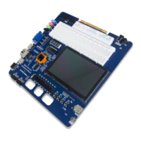
1. Select Place»Component.
2. Select an AND2 gate located in the PLD Logic group, Logic_gates family and click OK.
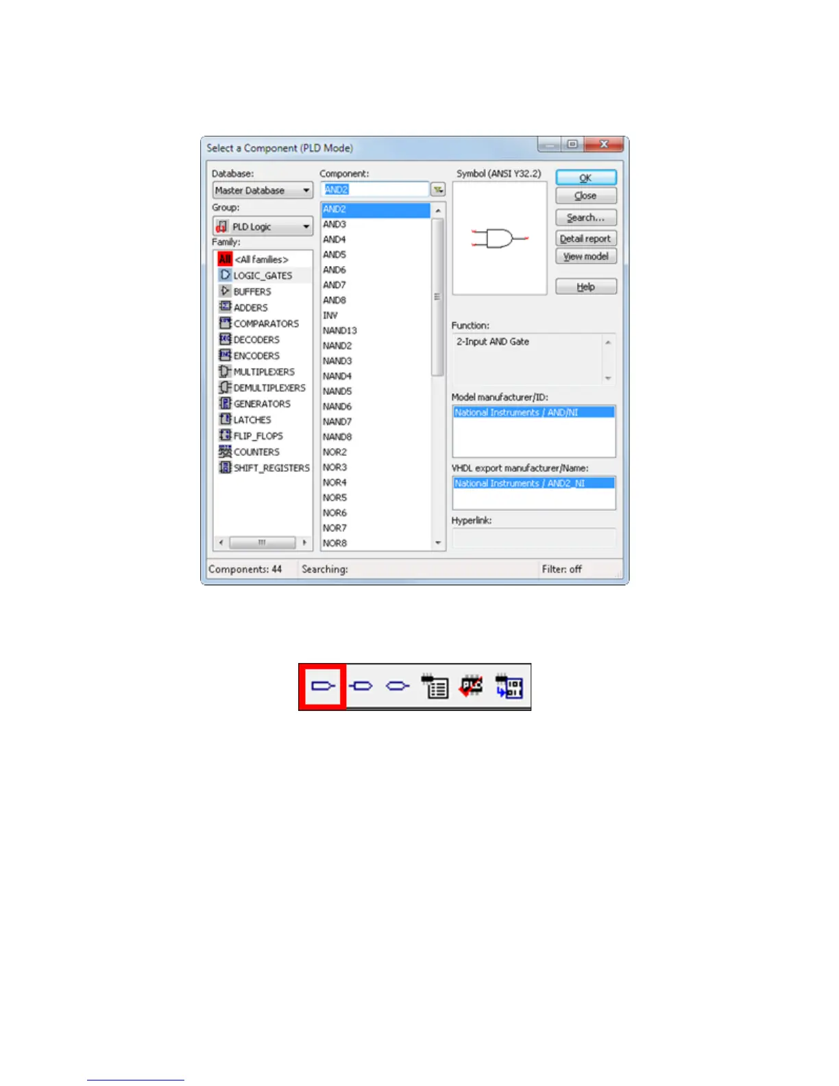
3. Place another connector for the AND gate input by clicking the Input connector icon on
the toolbar.
 Loading...