Do you have a question about the natus Dantec Keypoint G4 and is the answer not in the manual?
Category | Medical Equipment |
---|---|
Manufacturer | Natus Medical Incorporated |
Software | Keypoint.NET |
Stimulation Intensity | Up to 100 mA |
Report Generation | Yes |
Connectivity | USB, Ethernet |
Power Supply | 100-240 V AC, 50/60 Hz |
Amplifier Channels | 4, 8, or 12 |
Stimulator | Built-in |
Stimulator Type | Constant current |
Stimulation | Electrical |
Stimulation Frequency | 0.1 Hz to 50 Hz |
Stimulation Duration | 50 µs to 1 ms |
Data Management | SQL database |
Display | External monitor required |
Weight | Varies depending on configuration |
Dimensions | Varies depending on configuration |
Contact details for domestic and international technical assistance, including specific contacts for Germany and France.
Explanation of symbols like MD (Medical Device) and CE (European Conformity) found on medical devices.
Explanation of symbols indicating conformity with specific regions like UKCA and Swiss Authorized Representative.
Symbols indicating prescription status (Rx only) and identification (SN, LOT) for device traceability.
Provides basic information for setting up, operating, and maintaining the Dantec Keypoint G4 system.
System is an electrophysiological aid for assessing, diagnosing, and monitoring nervous system diseases.
Describes the Keypoint G4 system's design for acquiring, displaying, and managing electrophysiological data.
Identifies the system's use for diagnosing neuromuscular diseases in pediatric and adult patients.
States there are no known residual risks or side effects for procedures performed with the system.
Guidelines for securing the system, including policies, networked environments, and access controls.
Details on surface and needle electrodes, including material, cleaning, and connector standards.
Defines WARNING (risk of death/serious injury) and CAUTION (risk of injury/damage) labels.
Lists critical warnings regarding device use, cardiac application, flammables, and electrical connections.
Warnings about equipment use, electrical hazards, RF interference, and cleaning agents.
Cautions regarding HF surgical equipment, IEC 60601-1 compliance, and data backup.
Requirements for mains plug, prohibition of extension cords, and disconnection before servicing.
Details Class I protection and safety checks like insulation and leakage current testing.
Conditions for placing equipment within the patient environment, including protective earth.
Technical specifications on source voltage and calculation of maximum current density for electrodes.
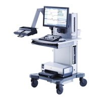
Diagram and list identifying key components of the Keypoint G4 workstation.
Step-by-step instructions for connecting signal and power interface cables.
Information on connecting HS LINK modules and potential restrictions due to power limits.
Details on various input/output connectors for stimulation, trigger, and headsets.
Explains the purpose of the isolation transformer for improved electrical safety and reduced leakage current.
Information on fuses, rating frequency, and specifications for the 6 auxiliary outlets.
Details on protection type, sterilization, patient vicinity, and suitability for flammable anesthetics.
Identification of buttons, keys, and indicators on the Keypoint G4 control panel.
Explanation of color-coded keys for navigating software tabs and controlling functions.
Using arrow keys to modify sweep speed and sensitivity levels.
Control knobs and arrow keys for adjusting stimulus intensity, duration, and repetition rate.
Details on stimulus intensity control knob, duration, and repetition rate arrow keys.
Functions for loudspeaker mute, volume, cursor mode, and trace/marker arrow keys.
Description of the HS Link Input Connector on the rear panel for internal connections.
Power ON indicator, isolated inputs, impedance test, and loudspeaker mute functions.
Details on different amplifier input connectors, including DIN-type and touch-proof options.
Features like Power ON indicator, isolated inputs, and impedance test for the EP amplifier.
Description of common array and head array input connectors for the EP amplifier.
Introduction to stimulators and features of the Advanced Stimulation Handgrip.
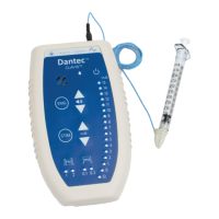
Details on Single CC and Multi CC stimulators, including their power indicators.
Describes the functions assigned to buttons 4, 5, 6, and 7 on the stimulation handgrip.
Details on operating Single and Multi CC stimulators, including power indicators.
Information on CC stimulator output ports, touch-proof connectors, and active electrode indication.
List of recommended stimulation electrode part numbers and types for investigations.
Description of functions for pedals A, B, and C of the optional footswitch.
Procedure for power up test and handling of hardware/software related alerts.
List of additional accessories compatible with Keypoint G4, including their part numbers.
Catalog of available software options for the Keypoint G4 system with corresponding part numbers.
Instructions on how to launch the Keypoint.NET application from the Windows desktop.
Overview of the Home Page options for creating studies, accessing the study list, and system settings.
Details on entering patient data, comments, and conclusions on the Patient Data page.
How to access and navigate the study list to view or edit existing studies.
Explanation of icons used in the study list to indicate status like uploading or completion.
Describes how to interact with studies using double-clicking and right-clicking menus.
Overview of the test menu tabs, tree view, and filter options for selecting tests.
Details on the anatomy box displaying available muscle and nerve sites for testing.
Steps for selecting the Motor test and choosing the Left or Right side.
Procedure for choosing the filter root and muscle/nerve from dropdown boxes.
Overview of the test screen layout, including numbered interface elements.
Instructions on how to select and activate new sites using mouse or control panel.
Using control panel arrow keys to modify sweep speed and sensitivity levels.
Modifying stimulation parameters like duration and repetition rate using mouse or control panel.
Explains causes of stimulator overload and actions to take, such as stopping stimulation.
Methods for inserting and moving markers on the trace using mouse or control panel.
Procedure for adjusting the vertical offset of traces using the trace handle.
Steps for conducting the impedance test and interpreting the results indicated by LED colors.
Explanation of Site and Segment tables, including reference limits and color coding.
Accessing optional windows like Display, Design, Impedance, and Signal Processing.
Overview of the Nerve Conduction Data page displaying results from the current study.
Adjusting recording and stimulation parameters for specific NCS tests.
Procedures for reassigning traces to correct stimulation sites or sides.
Description of the EMG acquire view, including numbered interface elements and scopes.
Explanation of EMG stage buttons and the scope bar displaying muscle and buffer status.
Methods for activating and controlling triggers using the mouse or control panel.
Using the control panel to adjust trigger level and select trigger slope.
Using window triggers and split screen view for enhanced signal analysis.
Operating the digital tape recorder for recording live tests and playing back recordings.
Using the Findings page for scoring and the Note Window for adding comments to tests.
Correcting errors by reassigning traces to the wrong muscle or patient side.
Visualizing Motor Unit Potential (MUP) data using different plot windows.
Describes actions when MUPs are found or not found during analysis.
Presentation of motor unit potential data in a table format on the MUP Data page.
Display of MUPs broken down into single units with a vertical dividing line.
Functions available when cursor is over a MUP, including deletion and opening in MUP Edit view.
Details on template information like amplitude, duration, phases, and editing.
Procedures for averaging two templates and deleting a template.
How to locate MUPs and add them to templates using mouse and context menus.
Method for removing a selected MUP from a template box.
Recommendations for regular data backup and how to perform screen prints.
Enabling demo mode for simulated signals and using right-click for hidden functions.
Schedule for system maintenance, safety inspections, and checks for exterior damage.
Steps recommended to resolve issues with noisy or inappropriate acquired data.
Guidelines for cleaning the system with a damp cloth, ensuring no liquid ingress.
Information on safe disposal of electrical equipment according to WEEE regulations.
Contact information for Natus technical support in different regions.
Details to have ready when contacting technical support for efficient problem resolution.
Specifies suitable environments for system use, excluding high electromagnetic disturbance areas.
Assessment of how EMC may affect essential performance and system functionality.
Important warnings and notes related to EMC, including suitability for residential environments.
Information on emission tests, compliance, and guidance for electromagnetic environments.
Details on immunity test levels for various electromagnetic phenomena as per IEC standards.
Specific immunity test levels for electrostatic discharges and radiated RF fields.
Immunity test levels for power ports and signal input/output parts.
Table detailing immunity levels for various RF frequencies and communication standards.
Technical details for amplifiers and averagers, including impedance, sensitivity, and sampling rate.
Specifications for sweep speeds, delay line, resolution, and display parameters.
Technical data for the electrical stimulator, including max output and weight of the system.
Details on stimulator output voltage, current, polarity, and safety features.
Specifications for the visual stimulator and patient safety regarding isolation.
Operating and storage conditions, including temperature, humidity, altitude, and pressure.
Specifications for the isolating transformer's rating frequency, fuses, and auxiliary outlets.
Details on data sampling resolution, digital filtering, and stored sampling frequencies.
Information on averager calculations using bit floating point numbers and autostop settings.
How the system ensures correct peak display using algorithms and sampling frequencies.