Danmarksvej 1B
DK-8660 Skanderborg
Tel.: +45 86 51 11 66
scoreboards@nautronic.com
nautronic.com
Installation instructions
Scoreboard connections
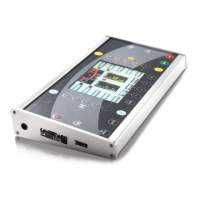
Shot clocks
NC26760
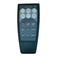
Naucon-1000 controlpanels
Backboard
« LED strips »
NA2164
NX33001
NG112 NG112
erminator resistor 330 ohm
tandard mounted.
AC
ch the terminated
connector to the last board
e net.
Main
scoreboard
Sideboard
“HOME”
top
Sideboard
“GUEST”
top
Sideboard
“HOME”
bottom
Sideboard
“GUEST
”
bottom
PLEASE NOTE …
Cables between control units
and scoreboards are not
provided.
NauNetcable specifications: CA
T5
cable with RJ45 connectors.
Maximum cable length 500 me-
ters. If the cable length exceeds
500 meters, contact Nautronic
for instructions.
3
 Loading...