42 About the Boiler
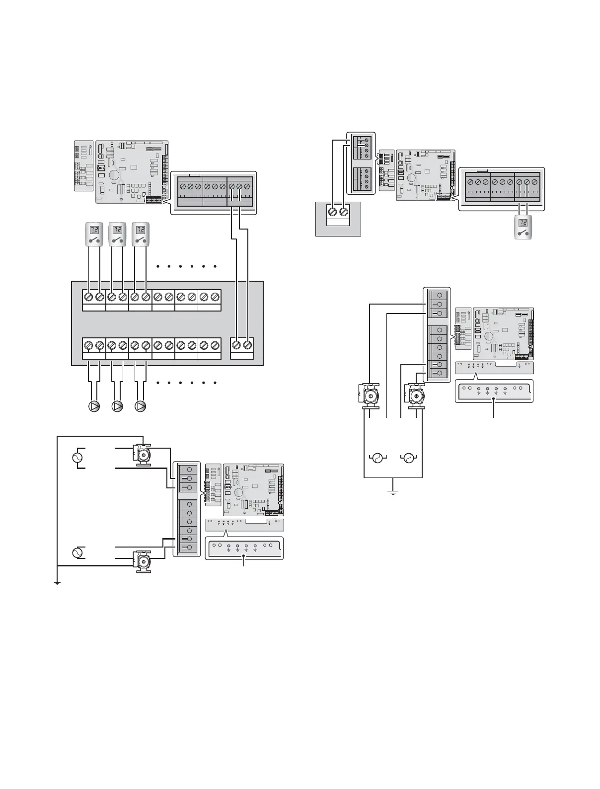
3.6.7 Wiring Diagram - Air Handler
Thermostat
%RLOHU3XPS
=21(3803 =21(3803 =21(3803
/B,1 /B287/B,1 /B287/B,11&/B287 12/B287 &20/B,1 /B287
%RLOHU6WDWH %RLOHU(UURU$+ '+:35,
18/7,6: )/2:6:
(;,7,1387 7(03(5$785(6(1625
/36:
287'225 '+:7$1.
a9,1 a9287
6<67(0
6833/<
6<67(0
5(7851
5:
76=21( 76=21( 76=21(
&
5:
&
5:
&
5:
&
76'+:
/:&2
$&9/
$&91
5:
76=21( 76=21( 76=21(
&
5:
&
5:
&
%RLOHU6WDWH %RLOHU(UURU
$+ '+:35,
<Air Handler>
<NFB>
<NFB>
System
Pump
(max 5A)
Boiler
Pump
(max 5A)
%RLOHU3XPS
=21(3803 =21(3803 =21(3803
/B,1 /B287/B,1 /B287/B,11&/B287 12/B287 &20/B,1 /B287
%RLOHU6WDWH %RLOHU(UURU$+ '+:35,
18/7,6: )/2:6:
(;,7,1387 7(03(5$785(6(1625
/36:
287'225 '+:7$1.
a9,1 a9287
6<67(0
6833/<
6<67(0
5(7851
5:
76=21( 76=21( 76=21(
&
5:
&
5:
&
5:
&
76'+:
/:&2
$&9/
$&91
%RLOHU3XPS
=21(3803 =21(3803 =21(3803
/B,1 /B287/B,1 /B287/B,11&/B287 12/B287 &20/B,1 /B287
$&9B1
$&9B/
$&9B/
$&9B1
$&
$&
Pump Ground
3.6.6 Wiring Diagram - Generic Zone System with
Circulators
%RLOHU3XPS
=21(3803 =21(3803 =21(3803
/B,1 /B287/B,1 /B287/B,11&/B287 12/B287 &20/B,1 /B287
%RLOHU6WDWH %RLOHU(UURU$+ '+:35,
18/7,6: )/2:6:
(;,7,1387 7(03(5$785(6(1625
/36:
287'225 '+:7$1.
a9,1 a9287
6<67(0
6833/<
6<67(0
5(7851
5:
76=21( 76=21( 76=21(
&
5:
&
5:
&
5:
&
76'+:
/:&2
$&9/
$&91
Zone1 T/S Zone2 T/S Zone3 T/S Zone4 T/S Zone5 T/S
Zone6 T/S
Zone1 PumpZone2 PumpZone3 PumpZone4 PumpZone5 PumpZone6 Pump
T/T
5:
76=21( 76=21( 76=21(
&
5:
&
5:
&
<NFB>
Generic Zone Controller
%RLOHU3XPS
=21(3803 =21(3803 =21(3803
/B,1 /B287/B,1 /B287/B,11&/B287 12/B287 &20/B,1 /B287
%RLOHU6WDWH %RLOHU(UURU$+ '+:35,
18/7,6: )/2:6:
(;,7,1387 7(03(5$785(6(1625
/36:
287'225 '+:7$1.
a9,1 a9287
6<67(0
6833/<
6<67(0
5(7851
5:
76=21( 76=21( 76=21(
&
5:
&
5:
&
5:
&
76'+:
/:&2
$&9/
$&91
%RLOHU3XPS
=21(3803 =21(3803 =21(3803
/B,1 /B287/B,1 /B287/B,11&/B287 12/B287 &20/B,1 /B287
$&9B1
$&9B/
$&9B1
$&9B/
$&
$&
<NFB>
System Pump
(max 5A)
Boiler Pump
(max 5A)
Pump Ground
 Loading...