43Installing the System Piping
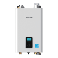
3.6.8 Wiring Diagram - DHW System with Indirect
Tank
<NFB>
Zone1 T/S Zone2 T/S Zone3 T/S Zone4 T/S Zone5 T/S
Zone6 T/S
Zone1 Valve Zone2 Valve Zone3 Valve Zone4 Valve Zone5 Valve Zone6 Valve
T/T
%RLOHU3XPS
=21(3803 =21(3803 =21(3803
/B,1 /B287/B,1 /B287/B,11&/B287 12/B287 &20/B,1 /B287
%RLOHU6WDWH %RLOHU(UURU$+ '+:35,
18/7,6: )/2:6:
(;,7,1387 7(03(5$785(6(1625
/36:
287'225 '+:7$1.
a9,1 a9287
6<67(0
6833/<
6<67(0
5(7851
5:
76=21( 76=21( 76=21(
&
5:
&
5:
&
5:
&
76'+:
/:&2
$&9/
$&91
5:
76=21( 76=21( 76=21(
&
5:
&
5:
&
5:
&
76'+:
5:
76=21( 76=21( 76=21(
&
5:
&
5:
&
5:
&
76'+:
DHW Priority
DHW
Aquastat
(Priority)
Generic Zone Controller
Note
When using zone controllers, the DHW demand lines
must be connected to the NFB boilers.
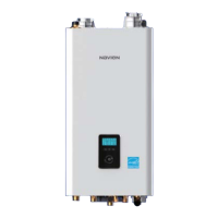
<NFB>
Boiler
Pump
(max
5A)
System
Pump
(max 5A)
%RLOHU3XPS
=21(3803 =21(3803 =21(3803
/B,1 /B287/B,1 /B287/B,11&/B287 12/B287 &20/B,1 /B287
%RLOHU6WDWH %RLOHU(UURU$+ '+:35,
18/7,6: )/2:6:
(;,7,1387 7(03(5$785(6(1625
/36:
287'225 '+:7$1.
a9,1 a9287
6<67(0
6833/<
6<67(0
5(7851
5:
76=21( 76=21( 76=21(
&
5:
&
5:
&
5:
&
76'+:
/:&2
$&9/
$&91
%RLOHU3XPS
=21(3803 =21(3803 =21(3803
/B,1 /B287/B,1 /B287/B,11&/B287 12/B287 &20/B,1 /B287
$&9B1
$&9B/
$&9B/
$&9B1
$&9B/
$&9B1
$&
$&
$&
7(03(5$785(6(1625
287'225 '+:7$1.
a9,1 a9287
6<67(0
6833/<
6<67(0
5(7851
Pump Ground
DHW
Pump
(max
5A)
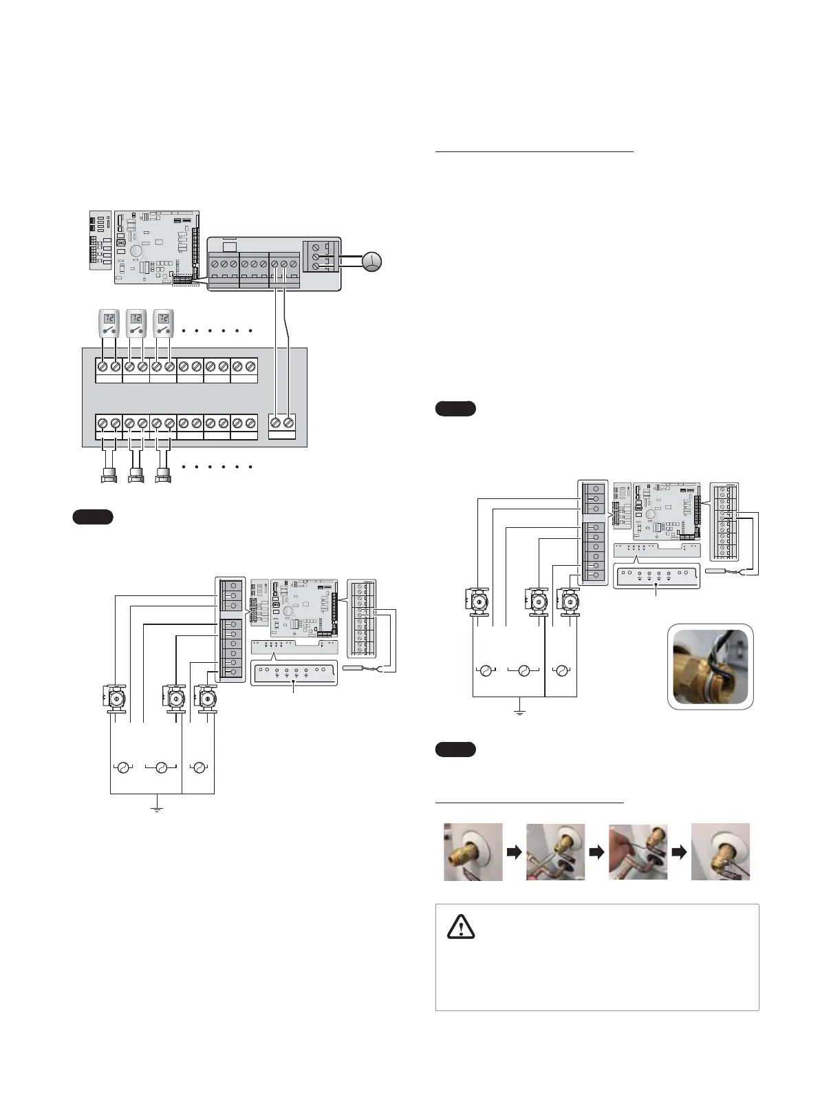
When connecting the DHW Tank Sensor
The Navien Universal Temperature sensor can be used as a DHW
Tank Sensor. When installing the Universal Temperature sensor to
the boiler, follow these guidelines:
Ɣ
This sensor is compatible for use with aquastat immersion wells.
Attach an aquastat immersion well to the DHW tank before
installing the sensor.
Ɣ
When installing the sensor to the tank, verify that the sensor is
completed inserted into the immersion well.
Ɣ
Install the included clip on the groove on the immersion well as
shown in the illustration.
Ɣ
Insert the wire through the available eyelet on the clip then
wrap it around the clip once to fix the sensor to the well.
Ɣ
Complete the installation by connecting the wires to the DHW
Tank terminals located on the PCB.
Note
When inserting the sensor into the immersion well,
heat conductive paste can be used to improve thermal
transfer between the two components.
%RLOHU3XPS
=21(3803 =21(3803 =21(3803
/B,1 /B287/B,1 /B287/B,11&/B287 12/B287 &20/B,1 /B287
%RLOHU6WDWH %RLOHU(UURU$+ '+:35,
18/7,6: )/2:6:
(;,7,1387 7(03(5$785(6(1625
/36:
287'225 '+:7$1.
a9,1 a9287
6<67(0
6833/<
6<67(0
5(7851
5:
76=21( 76=21( 76=21(
&
5:
&
5:
&
5:
&
76'+:
/:&2
$&9/
$&91
%RLOHU3XPS
=21(3803 =21(3803 =21(3803
/B,1 /B287/B,1 /B287/B,11&/B287 12/B287 &20/B,1 /B287
$&9B1
$&9B/
$&9B/
$&9B1
$&9B/
$&9B1
$&
$&
$&
7(03(5$785(6(1625
287'225 '+:7$1.
a9,1 a9287
6<67(0
6833/<
6<67(0
5(7851
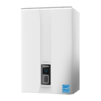
<NFB>
System
Pump
(max.
2.5 A)
Pump Ground
Boiler
Pump
(max.
2.5 A)
DHW
Pump
(max.
2.5 A)
Note
Use only Navien Universal Temperature sensor.
When installing the DHW Tank Sensor
WARNING
Use only the Navien Universal Temperature sensor
(#GXXX001769). The use of other sensors may result in higher
water temperatures than expected.
 Loading...