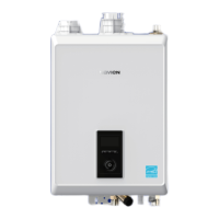
6. Loosen the three screws indicated below in Figure 2 and 3.
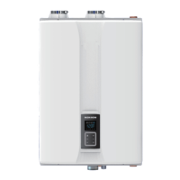
Figure 2. NHB isometric view
7. Remove the PCB assembly.
Figure 3. NHB Series PCB
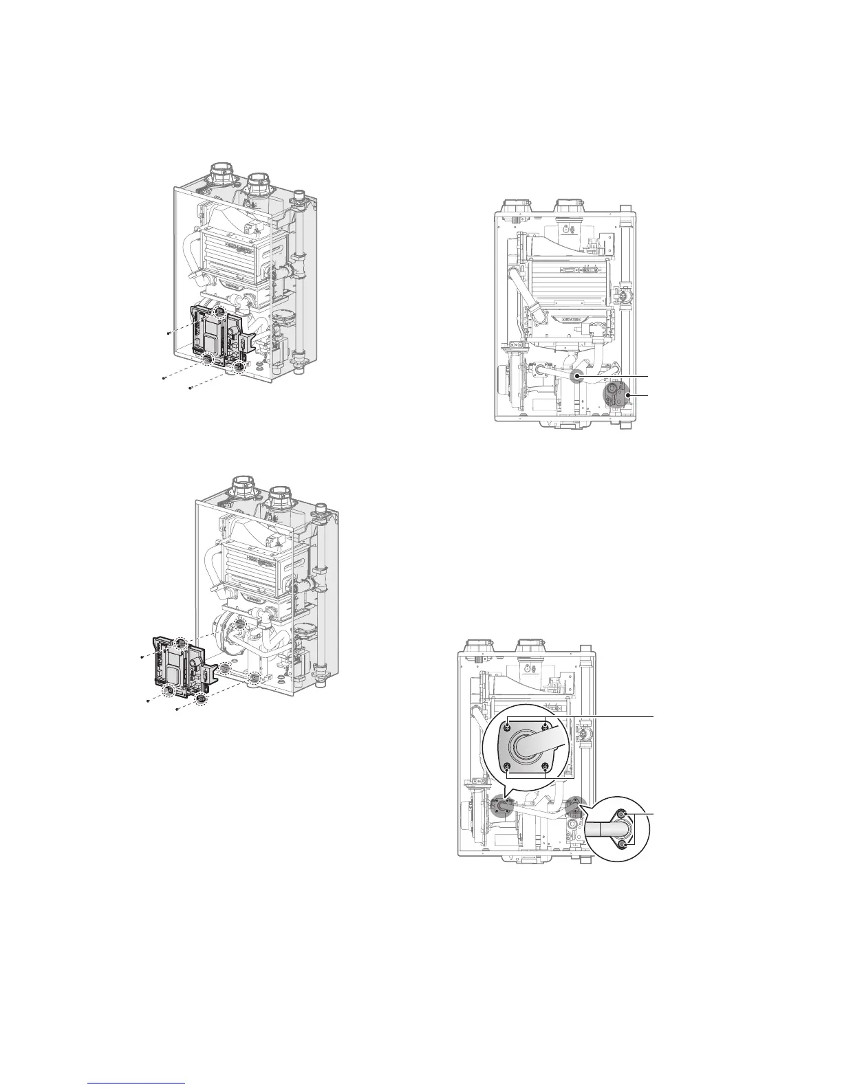
8. With the internal components exposed, locate the gas inlet
pipe and the gas valve in the middle of the unit, as shown in
Figure 4.
Gas Valve
Gas Inlet Pipe
Figure 4. NHB Series Internal Components
9. Use a Phillips screwdriver to remove the two screws at location
A - the connection below the gas valve where it connects
to the pipe. See Figure 5 for reference. Once the screws are
removed, carefully separate the pipe from the gas valve.
10. Once the gas inlet pipe is detached from the gas valve, find
location B - the connection above the gas valve where it is
attached to the fan motor assembly. Carefully remove the four
screws by hand using a Phillips screwdriver and pull the gas
valve away from the fan assembly to access the gas orifice.
Location B: Remove
4 screws here
Location A: Remove
2 screws here
Figure 5. Detaching Gas Valve from
Gas Inlet Pipe and Fan Motor Assembly
 Loading...