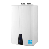
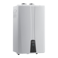
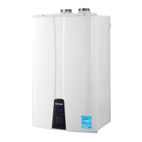
EasyManua.ls Logo

Navien NP-240 User Manual

Navien NP-240
89 pages
To Next Page IconTo Next Page
Page #1 background imageLoading...
Page #1 background image
NR-180(A) NP-180(A)
NR-210(A) NP-210(A)
NR-240(A) NP-240(A)
Navien
Conden
sing
Water Heater
Manua
l
- WHAT TO DO IF YOU SMELL GAS
Do not try to light any appliance.
Do not touch any electrical switch: do not use any phone in your building.
Immediately call your gas supplier from a n
eighbor’s phone. Follow the gas supplier’s
instructions.
If you cannot reach your gas supplier, call the fire department.
- Installation and service must be performed by a
qualified installer, service agency
or the gas supplier.
- Please return the “Manual” to t
he customer after installing.
If the information in these instructions is not followed exactly,
a fire or
explosion may result causing property damage, personal injury or death.
This product warranty is valid only used in the America and Canada
but automatically be voided for other countries. (for America and
Canada unit standard only)
- Do not store or use
gasoline or other flammable vapors and liquids in the vicinity
of this or other appliance.
Operation & Installation
Manual

Other manuals for Navien NP-240

Question and Answer IconNeed help?

Do you have a question about the Navien NP-240 and is the answer not in the manual?

Navien NP-240 Specifications

General IconGeneral
Fuel TypeNatural Gas / LPG
Water Connection3/4" NPT
Temperature Range98°F - 140°F
TypeTankless
Vent TypePVC, CPVC
Vent Size2"/3"
Voltage120V
Warranty15 years heat exchanger, 5 years parts
Max. Output BTU199, 900 BTU/hr

Summary

Safety Instructions

Safety Related Symbols

Explains symbols like DANGER, WARNING, CAUTION, and their meanings.

Safety Precautions

General Safety Precautions

Lists essential safety measures for installation, operation, and maintenance.

Hazard Warnings

DANGER Flammable Vapors

Highlights dangers associated with flammable vapors near the water heater.

Emergency Procedures

DANGER WHAT TO DO IF YOU SMELL GAS

Provides immediate actions to take if a gas leak is detected.

DANGER COMPROMISED VENTING SYSTEM

Warns about risks from compromised venting, including CO poisoning.

Accessories

Included with the Water Heater

Lists all items supplied directly with the water heater unit.

Optional Accessories

Lists additional accessories that can be purchased separately.

Specifications

Key Components: NR-A

Key Components: NP-A

Dimensions: NR-A, NP-A

Key Components: NR

Key Components: NP

Dimensions: NR, NP

Installation Warnings

General Installation Warnings

Additional safety issues to follow during installation.

Getting Started

CHECK THE RATING PLATE

Verifying unit's gas type, pressure, and electrical supply.

Rating Plate Checks

Humidity Location Warning

Caution against installing in humid locations to prevent malfunction.

Locating the Water Heater

Location Considerations

Factors to consider for optimal unit placement and customer satisfaction.

Mounting the Unit to the Wall

Instructions for secure wall mounting of the water heater.

Plumbing

Plumbing and Water Connection Guidelines

Best practices for water piping and connections.

Water Piping Guidelines

Guidelines for pipe sizing, insulation, and filter cleaning.

Space Heating Considerations

Considerations for using the unit for space heating applications.

Pressure Relief Valve Installation

WARNING on Pressure Relief Valve

Emphasizes importance and safety of pressure relief valve installation.

Condensate Management

Disposal of Condensate

Connecting drain lines and cleaning the siphon.

Gas Piping

Gas Supply Line Pressures

Gas Pipe Sizing

Measuring Inlet Gas Pressure

Venting

Venting Hazards

Warns about risks from improper venting and CO.

Venting Material Requirements

Specifies approved materials like PVC, CPVC, Polypropylene.

Venting Guidelines

Best practices for vent system installation.

Venting Types and Air Supply

Navien Direct Vent System

Explains the factory direct vent setup.

Navien Non-Direct Vent System

Guidance for non-direct vent installations.

Combustion Air Requirements

Non-Direct Vent Air Supply

Minimum air supply openings for non-direct vent.

Exhaust Vent Pipe Materials

Material Recommendations

Approved vent pipe materials for USA and Canada.

Vent Material Selection Note

Important limitations on vent materials and temperature.

Canadian Venting Requirements

Specific Canadian regulations for vent piping.

Venting Clearances

Allowable Venting Lengths

Allowable 3" Venting

Max lengths and elbow equivalents for 3" venting.

Allowable 2" Venting

Max lengths and elbow equivalents for 2" venting.

Indoor Venting Configurations

Vent Configuration Options

Diagrams of typical indoor vent setups.

3" 2-pipe Side Wall Vent

Diagram illustrating 3" side wall venting.

Non-concentric Side Wall Vent

Diagram of non-concentric side wall venting.

Vertical Vent Termination

3" 2-pipe Vertical Vent

Diagram of vertical vent termination.

Concentric Vent Termination

Sidewall Installation Diagram

Diagram for concentric sidewall installation.

Roof Installation Diagram

Diagram for concentric roof installation.

Outdoor Venting

Contaminated Air Warning

Warning about air contamination impacting the unit.

Outdoor Venting Guidelines

Guidelines for outdoor venting installations.

Outdoor Venting Clearances

Required clearances for outdoor installations.

Additional Venting Warnings

Vent Terminal Placement Warning

Additional safety warnings for vent terminal placement.

Electrical Connections

Electrical Code Compliance

Follows local electrical codes and NEC/CGA standards.

Wiring: Grounding and Surges

Factory plug, direct wiring, grounding, surge protector use.

Remote Controller Installation

Remote Controller Model NR-10DU

Identifies the remote controller model.

Remote Controller Location

Factors for choosing a remote controller installation site.

PCB Board Settings

Water Heater Temperature Settings

Explains PCB DIP switches for temperature adjustment.

Temperature Setting Warning

Warning about high water temperatures and scalding risk.

Cascade Connection and Set-up Procedures

Step 1: Plumbing

Plumbing guidelines for connecting multiple units.

Case I: NR-A, NP-A Recirculation

Diagram and notes for NR-A/NP-A recirculation setup.

Cascade Connection and Set-up Procedures

Case II: NR, NP MODEL Recirculation

Diagram and notes for NR/NP recirculation setup.

Cascade Connection and Set-up Procedures

Case III: NR, NP + NR-A, NP-A Recirculation

Diagram for mixed NR/NP and NR-A/NP-A cascade.

Case IV: CH + NR-A, NP-A Recirculation

Diagram for CH + NR-A/NP-A cascade with space heating.

Cascade Connection and Set-up Procedures

Case V: DHW Storage Tank Mode

Diagrams for DHW storage tank integration.

Cascade Connection and Set-up Procedures

DIP Switch Setting for Cascade

Explanation of DIP switch usage for mode selection.

The Common Vent

Using the Common Vent Tables

Guide on determining vent sizes using tables.

Determining Common Vent Size

Steps to size a common vent based on appliance load.

Cascade System Plumbing Pipe Size

Cable Connection and DIP Switch Setup

Step 3: Cable Connection

Details on connecting cables and setting DIP switches.

Communication Setup

Master Unit Setup

Procedure for setting up the master unit.

Communication Setup

Slave Unit Setup

Procedure for setting up slave units.

Master Unit Change

How to change the master unit.

Slave Unit Addition/Removal

Adding or removing slave units from the system.

Communication Setup

Slave Unit Setup (Additional)

Setting up additional slave units.

Cascade System Error Display

How errors are displayed in a cascade system.

Water Heater DIP Switch Settings

Set of 6 Switches: Settings

Settings for the 6-switch DIP set.

Burner Operation Mode Select (Not Used)

Explains burner operation modes, marked as not used.

Water Heater DIP Switch Settings

Model Selection (DIP 5 & 6)

DIP switch settings for model selection.

Operating Mode Selection (8 Switches)

Settings for the 8-switch DIP set.

Water Heater DIP Switch Settings

Pump & Recirculation Modes (DIP 4 & 5)

DIP switch settings for pump and recirculation modes.

Temperature Selection (DIP 7 & 8)

DIP switch settings for temperature selection.

Water Heater DIP Switch Settings

DHW Storage/Solar Mode (DIP 4)

DIP switch settings for DHW Storage/Solar Mode.

Factory DIP Switch Settings

Factory default DIP switch configurations for various models.

Completing the Install

Installation Checklist Overview

Checklist to verify installation completion and correctness.

Location and Mounting Checklist

Checklist items for location and mounting.

Water Supply Checklist

Checklist items for water supply connections.

Completing the Install

Pressure Relief Valve Checklist

Checklist items for pressure relief valve installation.

Gas Supply Checklist

Checklist items for gas supply installation.

Completing the Install

Venting Checklist

Checklist items for proper venting.

Electrical Wiring Checklist

Checklist items for electrical wiring.

Completing the Install

DIP Switch Settings Checklist

Checklist for correct DIP switch configuration.

Final Checks and Advisories

Final homeowner advisories and checks.

Safety Instructions

DANGER HOT WATER TEMPERATURE SETTING

Hazards of high water temperatures and scalding risk.

Navien Warranty

General Warranty Terms

General warranty terms and conditions.

Applicable Warranty Periods

Warranty periods for heat exchangers and parts.

Effective Date of Warranty

Defines the start date of warranty coverage.

Heat Exchanger Warranty Specifics

Specific warranty terms for heat exchangers.

Parts Warranty (Excluding Heat Exchanger)

Warranty terms for all other parts.

Usage Restriction: Space Heating (NR-(A) Series)

Restriction on using NR-(A) series for space heating.

Navien America, Inc. Limited Warranty

Labor Allowance

Details on labor allowance for warranty service.

Warranty Transferability

Conditions for warranty transferability.

Warranty Exclusions

Conditions not covered by the warranty.

Model Description and Legend

Model Description Legend

Explains model designations (NR, NP, A).

General Parts Identification

NR-A / NP-A Water Heater Parts

Identifies parts of NR-A/NP-A models.

General Parts Identification

NR / NP Water Heater Parts

Identifies parts of NR/NP models.

Remote Controller Overview

LCD Monitor Functions

Explains functions displayed on the LCD screen.

LED Indicator Meanings

Explains the meaning of LED indicators.

LCD Monitor Indicators

Details specific indicators like energy saving, hot water use.

Remote Controller Setup

Turning the Remote Controller On/Off

Steps to power the remote controller on and off.

Setting the Clock

Adjusting the Temperature

Temperature Setting Warning

Warning about high water temperatures and scalding.

Hot Water Tap Temperature Adjustment

Using the remote controller to adjust temp via hot water tap.

Hot Water Temperature Adjustment

Powering On the Remote Controller

How to turn the remote controller on.

Setting the Temperature

Instructions for setting temperature using Up/Down keys.

Hot Water Temperature Adjustment

Temperature Adjustment (125-140°F)

Adjusting temps between 125-140°F.

High Temperature Adjustment (140-185°F)

Adjusting temps above 140°F for specific models.

Hot Water Temperature Adjustment

Turning Hot Water ON

How to turn hot water ON and indicators.

Turning Hot Water OFF

How to turn hot water OFF and indicators.

"A" Series Recirculation Timer Setting

Check Current Time Setting

Ensure remote controller time is set correctly.

Activate Circulation Timer Setting

Steps to activate circulation timer setting.

Adjusting Circulation Periods

Adjusting circulation periods on the 24hr clock.

"A" Series Recirculation Timer Setting

Set Circulation Timer Start Time

Setting the start time and periods for circulation.

Deactivate Circulation Periods

How to deactivate specific circulation periods.

Lock Function Setting

Well Pump Setting Function

Set Number of Initial Activating Water Heaters (Cascade)

Pump Activation Setting (Hot Water Used)

DHW Storage Tank Temperature Setup

DHW Storage Tank Temperature Setup

Applications

"A" Series Built-In Circulation Function

Explains built-in circulation modes for "A" series.

"A" Series Two Operational Modes

Details the two operational modes for "A" series.

"A" Series Internal Recirculation Mode

"A" Series External Recirculation Mode

Related product manuals