3
Venting
>
Electrical Connections
>
Vent Termination Options
Indoor Horizontal Vent Termination Vertical vent termination
12" (300mm) min.
12" (300mm) min.
Interior view
Intake Air
Exhaust Gas
12" (300 mm) min.
Exterior view
12" min. from any
obstruction above,
below, left, or right
12" (300 mm) min.
12" (300 mm) min.
Sidewall vent termination
Concentric Vent Termination
Sidewall installation
Combustion Air
Combustion Air
1" (25mm) min
Maintain 12" min.
clearance above
highest anticipated
snow level or grade.
Vent
Roof installation Image of outdoor vent cap
Vent
Vent
Combustion Air
Maintain 12" min.
(18" min. for Canada)
clearance above
highest anticipated
snow level maximum
of 24" above roof.
Combustion
Air
Side
Bottom
Intake Air
Exhaust Gas
Top
Front
Side
Back
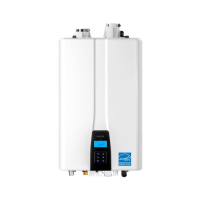
Venting Length
4” pipe venting 3” pipe venting
8
1
3
7
2
Maximum Length 150'
Maximum number
of elbows: 8
3-to-4 inch
6
1
3
4
5
2
Maximum number
of elbows: 6
Maximum Length 70"
· 90˚ elbow = 5 linear feet of venting
· 45˚ elbow = 3 linear feet of venting
· 90˚ elbow = 5 linear feet of venting
· 45˚ elbow = 3 linear feet of venting
Exhaust Vent Piping Materials
Venting requirements dier in the US and Canada. Consult the following chart or the
most recent edition of ANSI Z223.1/NFPA 54 or CAN/CGA B149.1, as well as all
applicable local codes and regulations when selecting vent pipe materials. Do not use
cellular core PVC (ASTM F891), cellular core CPVC, Radel® (polyphenolsulfone) for the
exhaust vent.
Navien recommended venting materials
Locale Recommended Vent Materials
USA
· PVC/CPVC Schedule 40 or 80 (Solid Core) - UL1738-certied materials are
approved for use
· Approved Polypropylene*
· Approved Stainless Steel
Canada*
· Type BH Special Gas Vent Class IIA (PVC)
· Type BH Special Gas Vent Class IIB (CPVC)
· Type BH Special Gas Vent Class IIC (Polypropylene/Stainless Steel)
* Refer to the manufacturer’s literature for detailed information on approved vent materials.
** For installation in Canada, eld-supplied plastic vent piping must comply with CAN/CGA B149.1 (latest
edition) and be certied to the Standard. For Type BH Gas Venting Systems, ULC-S636. Components of
this listed system must not be interchanged with other vent systems or unlisted pipes or ttings. All
plastic components and specied primers and glues of the certied vent system must be from a single
system manufacturer and must not be intermixed with another system manufacturer’s parts. The
supplied vent connector and vent termination are certied as part of the water heater.
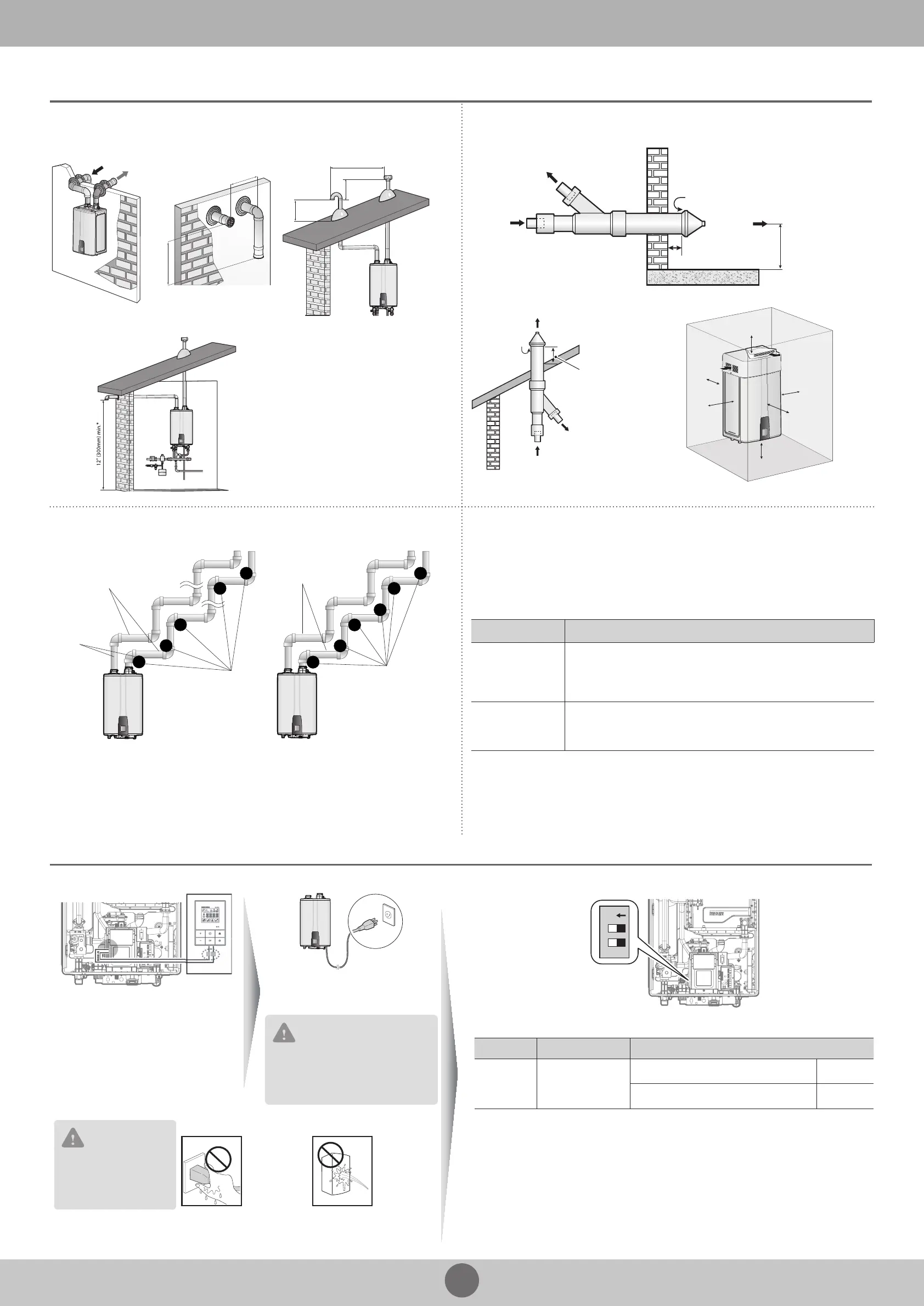
Remote Controller Connection Power Connection
120 V AC 60 Hz
Min. 2 Amp current with proper
grounding
CAUTION
Using abnormally high or low AC
voltage may cause abnormal operation,
thereby causing re which reduces the
life expectancy of this product.
CAUTION
Disconnect the power to
the water heater before
installing the remote
controller.
Safety
DO NOT touch
the power
cord with wet
hands.
DO NOT allow
the water
heater to be
exposed to
excessive
amounts of
water.
Conrmation of DIP Switch Settings
1 2
ON
· 2-switch Panel:
Switch Function Setting
2 Temperature Lock
Temperature can be set. OFF
Temperature cannot be set. ON
 Loading...