Do you have a question about the Navien NR-180A and is the answer not in the manual?
Defines safety terms and emphasizes following instructions to avoid hazards.
Lists and explains safety symbols used in the manual for hazard identification.
Explains symbols used within the instructions to highlight important information.
Details crucial safety precautions related to flammable materials and vapors.
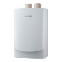
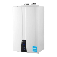
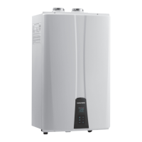
Overview of Navien Regular (NR) and Navien Premium (NP) series water heaters.
Diagrams and lists of key components for different model series.
Detailed layout and part numbers for the NR-A model.
Detailed layout and part numbers for the NP-A model.
Detailed layout and part numbers for the NR model.
Detailed layout and part numbers for the NP model.
Provides key specifications like heat capacity, dimensions, and gas type.
Illustrates connection diameters and overall dimensions.
Specific dimension details for NR-A and NP-A models.
Specific dimension details for NR and NP models.
Visual representation of the system's water and gas flow.
Schematic and flow diagram specific to the NR-A model.
Schematic and flow diagram specific to the NP-A model.
Schematic and flow diagram specific to the NR model.
Diagram illustrating the unit's operational sequence.
Configuration settings for dip switches on the PCB.
Electrical wiring diagrams for different models.
Wiring diagram for the NR-A model.
Wiring diagram for the NP-A model.
Wiring diagram for the NR model.
Wiring diagram for the NP model.
Identifies key points on the PCB for electrical diagnostics.
Detailed descriptions of major components and their functions.
Description of the Printed Circuit Board (PCB) functions and failure events.
Details on the thermal fuse, its function, and failure diagnostics.
Information on the transformer's role in power supply and diagnostics.
Description of high limit and exhaust limit switches, including function and failure.
Details on thermistors for temperature measurement and error detection.
Explanation of the fan motor's function and troubleshooting steps.
Description of the flame rod assembly for ignition sensing.
Information on the ignition transformer for spark generation.
Details on the Air Pressure Sensor (APS) for airflow control.
Description of the manifold's role in gas distribution.
Information on the Gas Pressure Sensor (GPS) for combustion control.
Description of the burner assembly and its combustion function.
Explanation of the water adjustment valve for flow control.
Details on the flow sensor for measuring water flow rate.
Description of the primary heat exchanger's function.
Description of the secondary heat exchanger's function.
Details on the buffer tank for temperature stability in 'A' series.
Explanation of the circulation pump in 'A' series for hot water circulation.
Description of the bypass mixing valve for temperature control.
List of error codes with their reasons and diagnostic actions.
Details on '01Error' related to heat exchanger boiling.
Troubleshooting for '03Error' indicating ignition failure.
Troubleshooting for '04Error' related to false flame detection.
Troubleshooting for '08Error' related to hot water temperature sensor short-circuit.
Troubleshooting for '07Error' related to hot water temperature sensor open.
Troubleshooting for '09Error' related to fan motor RPM error.
Troubleshooting for '10Error' indicating air pressure error.
Troubleshooting for '12Error' related to loss of flame during combustion.
Troubleshooting for '15Error' indicating internal PCB error.
Troubleshooting for '16Error' related to bimetal overheating.
Troubleshooting for '21Error' indicating heat exchanger input sensor open.
Troubleshooting for '22Error' indicating heat exchanger input sensor short-circuit.
Troubleshooting for '27Error' related to air volume sensor error.
Troubleshooting for '30Error' related to exhaust gas temperature error.
Troubleshooting for '32Error' related to direct water temperature sensor open.
Troubleshooting for '33Error' related to direct water temperature sensor short-circuit.
Troubleshooting for '34Error' indicating water adjustment valve error.
Troubleshooting for '35Error' related to gas pressure sensor error.
Troubleshooting for '36Error' indicating communication error.
Troubleshooting for '37Error' related to internal water leak.
Troubleshooting for '38Error' indicating pump error.
Troubleshooting for '39Error' related to flow sensor error.
Troubleshooting for '44Error' related to temperature sensor connection error.
Troubleshooting for '45Error' indicating bypass mixing valve error.
Troubleshooting for '48Error' related to gas pressure error.
Guides for troubleshooting issues based on specific symptoms.
Diagnosing and resolving various types of noise from the unit.
Troubleshooting common hot water related issues.
Steps to troubleshoot circuit breaker trips.
Lists precautions and tools required for water heater inspection.
Procedure for measuring and setting gas pressure.
Detailed steps for checking the inlet gas pressure.
Instructions for adjusting the gas-air ratio for optimal combustion.
Procedure for draining water from the unit and cleaning the filter.
Instructions for cleaning the intake air filter.
Procedure for flushing the heat exchanger with a cleaning solution.
General safety precautions and procedures for replacing parts.
Step-by-step instructions for replacing key components.
Procedure for replacing the Printed Circuit Board (PCB).
Procedure for replacing the fuse.
Procedure for replacing the transformer.
Procedure for replacing the fan motor.
Procedure for replacing the flame rod assembly.
Procedure for replacing the ignition transformer.
Procedure for replacing the Air Pressure Sensor (APS).
Procedure for replacing the manifold assembly.
Procedure for replacing the main gas valve.
Procedure for replacing the Gas Pressure Sensor (GPS).
Procedure for replacing the condensation trap.
Procedure for replacing the water adjustment valve.
Procedure for replacing the flow sensor.
Procedure for replacing the buffer tank in 'A' series units.
Procedure for replacing the circulation pump in 'A' series units.
Procedure for replacing the 3-way valve in 'A' series units.
Procedure for replacing the 2-way valve in NP-A/NP series.
Procedure for replacing the bypass mixing valve in 'Non-A' series.
Diagram and steps for disassembling the unit's case.
Diagram and steps for disassembling the burner assembly.
Diagram for disassembling the water way components of the NR-A model.
Diagram for disassembling the water way components of the NR model.
Diagram for disassembling the water way components of the NP-A model.
Diagram for disassembling the water way components of the NP model.
Template for recording annual inspection results.
Checklist items for visual inspection and system checks.
Checklist items for routine maintenance tasks.
| Brand | Navien |
|---|---|
| Model | NR-180A |
| Category | Water Heater |
| Language | English |