Do you have a question about the Navien NR-240 and is the answer not in the manual?
Safety warning regarding warranty validity outside North America.
States Navien's warranty for materials and workmanship under normal use.
Details coverage periods for heat exchangers and other parts.
Specifies proof of purchase requirements for warranty service.
Defines the applicability of the service manual to Navien Tankless Water Heater NR/NP Series.
Outlines important guidelines for manual accessibility and understanding.
Explains symbols and notations used within the manual for clarity.
Defines potential hazards and emphasizes following instructions to avoid injury.
Lists and explains various safety symbols used in the manual.
Explains symbols used to highlight important information in the instructions.
Instructions to keep the area around the water heater clear of flammable materials.
Warning about explosion risk from flammable vapors near the water heater.
Emphasizes proper venting to prevent fire, explosion, or asphyxiation.
Advises on safe hot water temperatures to prevent scalding.
Provides critical steps to follow in case of a gas leak.
Lists essential safety guidelines before operating or servicing the unit.
Highlights the need to follow local codes and manufacturer instructions for installation.
Advises checking gas type and AC voltage compatibility before servicing.
Warns against field conversion and its warranty implications.
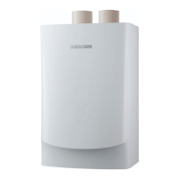
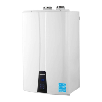
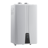
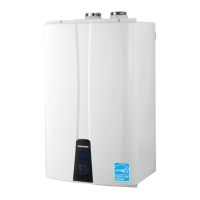
Introduces Navien Regular (NR) and Navien Premium (NP) series water heaters.
Details the layout and part numbers for the NR-A model.
Details the layout and part numbers for the NP-A model.
Details the layout and part numbers for the NR model.
Details the layout and part numbers for the NP model.
Provides key specifications like heat capacity, dimensions, and gas type.
Shows the physical dimensions and connection diameters for NR-A/NP-A.
Shows the physical dimensions and connection diameters for NR/NP.
Illustrates the internal workings and flow paths of the NR-A model.
Illustrates the internal workings and flow paths of the NP-A model.
Illustrates the internal workings and flow paths of the NR model.
Illustrates the internal workings and flow paths of the NP model.
Visual representation of the unit's operational sequence.
Explains the function and configuration of PCB dip switches.
Wiring diagram for the NR-A model.
Wiring diagram for the NP-A model.
Wiring diagram for the NR model.
Wiring diagram for the NP model.
Describes the function, failure events, error codes, and diagnostics of the PCB.
Details the thermal fuse's role in protecting the unit from overheating.
Explains the transformer's function in supplying power to the PCB and components.
Describes the function of safety switches that prevent overheating.
Explains thermistors' role in measuring temperatures and detecting failures.
Details the fan motor's function in providing combustion air and exhausting flue gas.
Describes the flame rod's function in detecting ignition and flame presence.
Explains the ignition transformer's role in generating spark for ignition.
Details the Air Pressure Sensor's function in controlling air supply for combustion.
Describes the manifold's function in distributing gas to the burners.
Explains the main gas valve's role in controlling gas supply to the unit.
Details the Gas Pressure Sensor's function in modulating gas supply for stable combustion.
Describes the burner's function in mixing gas and air for combustion.
Explains the valve's function in controlling water flow for temperature regulation.
Details the flow sensor's role in measuring water flow rate.
Describes the primary heat exchanger's function in heat transfer.
Explains the secondary heat exchanger's role in heat transfer.
Details the buffer tank's function in providing steady hot water temperature.
Explains the circulation pump's role in internal/external hot water circulation.
Describes the valve's function in modulating outlet water temperature.
Lists error codes, their reasons, and diagnostic/reset actions.
Details error conditions, description, and check items for 01Error (Boiling).
Explains error conditions, description, and check items for 03Error (Ignition Fail).
Details error conditions, description, and check items for 04Error (False-flame detection).
Explains error conditions, description, and check items for 07Error (Hot water temperature sensor open).
Details error conditions, description, and check items for 08Error (Short-circuit of hot water temperature sensor).
Explains error conditions, description, and check items for 09Error (Fan motor RPM error).
Details error conditions, description, and check items for 10Error (Air pressure error).
Explains error conditions, description, and check items for 12Error (Loss of flame during combustion).
Details error conditions, description, and check items for 15Error (MICOM error).
Explains error conditions, description, and check items for 16Error (Bimetal overheated).
Details error conditions, description, and check items for 21Error (Heat exchanger input temperature sensor open).
Explains error conditions, description, and check items for 22Error (Heat exchanger input temperature sensor shortcircuit).
Details error conditions, description, and check items for 27Error (Air volume sensor error).
Explains error conditions, description, and check items for 30Error (Exhaust gas temperature error).
Details error conditions, description, and check items for 32Error (Direct water temperature sensor open).
Explains error conditions, description, and check items for 33Error (Direct water temperature sensor short-circuit).
Details error conditions, description, and check items for 34Error (Water Adjustment Valve error).
Explains error conditions, description, and check items for 35Error (Gas pressure sensor error).
Details error conditions, description, and check items for 36Error (Communication Error).
Explains error conditions, description, and check items for 37Error (Internal water leak).
Details error conditions, description, and check items for 38Error (Pump error).
Explains error conditions, description, and check items for 39Error (Flow sensor error).
Details error conditions, description, and check items for 44Error (Temperature sensor connection error).
Explains error conditions, description, and check items for 45Error (Bypass Mixing Valve error).
Details error conditions, description, and check items for 48Error (Gas pressure error).
Guides troubleshooting for various types of noise issues.
Provides troubleshooting steps for problems related to hot water supply.
Addresses troubleshooting steps when the circuit breaker operates.
Lists necessary precautions and tools for performing an inspection.
Step-by-step guide for checking the inlet gas pressure.
Detailed procedure for adjusting the gas-air ratio for optimal combustion.
Instructions for draining water from the unit and cleaning the inlet filter.
Procedure for cleaning the intake air filter.
Steps for flushing the heat exchanger to maintain performance.
General guidelines and safety precautions for replacing parts.
Detailed instructions for replacing individual components.
Step-by-step guide for replacing the Printed Circuit Board (PCB).
Instructions for replacing the fuse.
Detailed steps for replacing the transformer.
Guide for replacing the fan motor responsible for combustion air.
Instructions for replacing the flame rod assembly.
Steps for replacing the ignition transformer.
Guide for replacing the Air Pressure Sensor (APS).
Detailed instructions for removing and replacing the manifold.
Steps for replacing the main gas valve.
Guide for replacing the Gas Pressure Sensor (GPS).
Instructions for replacing the condensation trap.
Steps for replacing the water adjustment valve.
Guide for replacing the flow sensor.
Instructions for replacing the buffer tank on 'A' Series models.
Steps for replacing the circulation pump on 'A' Series models.
Instructions for replacing the 3-way valve on 'A' Series models.
Steps for replacing the 2-way valve on NP-A/NP Series.
Instructions for replacing the bypass mixing valve on 'Non-A' Series.
Illustrates the process of disassembling the unit's case.
Shows the steps for disassembling the burner assembly.
Diagram for disassembling the water way components of the NR-A model.
Diagram for disassembling the water way components of the NR model.
Diagram for disassembling the water way components of the NP-A model.
Diagram for disassembling the water way components of the NP model.
Summarizes the recommended annual inspection items.
Provides a checklist for annual inspection items.
Provides a checklist for maintenance procedures.
| Brand | Navien |
|---|---|
| Model | NR-240 |
| Category | Water Heater |
| Language | English |