DIAGNOSTICMANUAL
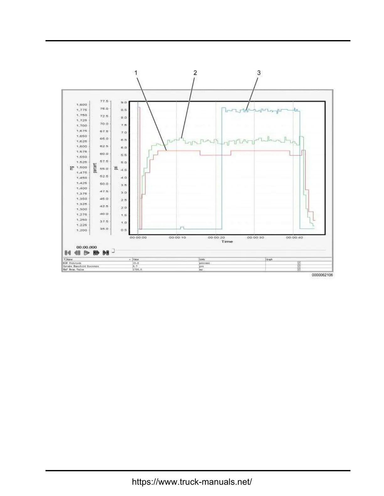
4.2.GRAPH2:AIRMANAGEMENTSYSTEMTEST(BAD)
1.IntakeManifoldPressure(IMP)
(psi)[Red]
2.MassAirFlow(MAF)MeanValue
(MMV)(mg)[Green]
3.ExhaustGasRecirculation(EGR)
valveposition(percent)[Blue]
Figure6Graph2:AirManagementSystemTest(Bad)
GraphAnalysis:
ThisgraphshowsanAirManagementSystem(AMS)notoperatingasdesignedduringtheAirManagement
Test(AMT).TheAMTgivespassorfailresults.ItallowstheusertovalidatetheAMSbymonitoringtheeffects
eachactuatorhasonIntakeManifoldPressure(IMP).IMPisnormallybetween2psi(14kPa)to6psi(41kPa)
onenginerampupduringAMT .IftheExhaustGasRecirculation(EGR)valveisnotoperatingasdesigned,
IMPwillnotrespondtochangesinEGRvalveposition.Excesssootwillthenbegeneratedbytheengine
causingfrequentregenerationoftheaftertreatmentsystem.
Actions:
1.WhenEGRvalveiscommandedON,verifyIntakeManifoldPressure(IMP)signalvaluedrops.In
thisgraph,IMPdoesnotdropwhenEGRvalveiscommandedON.
NOTE–EGRvalvepositionwillneverreadlessthan35%andisconsideredclosed.
53
https://www.truck-manuals.net/

 Loading...


