English-55English-54
English
Stop bit 1 bit
Communication code ASCII
This Display uses RXD, TXD and GND lines for RS-232C control.
The reverse type cable (null modem cable) (not included) should be used for
RS-232C control.
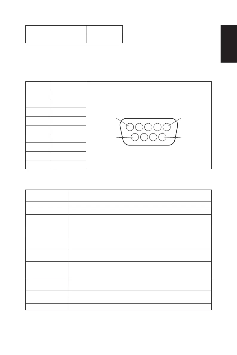
2) PIN ASSIGNMENT
RS-232C input/output
Pin No RS-232C
D-Sub 9-pin (Monitor side)
1 NC
2 RXD
3 TXD
4 NC
5 GND
6 NC
7 NC
8 NC
9 NC
This Display uses RXD, TXD and GND lines for RS-232C control.
Control command diagram
Function
(Monitor ID = 1)
Code Data
Power ON 01 30 41 30 41 30 43 02 43 32 30 33 44 36 30 30 30 31 03 73 0d
Power OFF 01 30 41 30 41 30 43 02 43 32 30 33 44 36 30 30 30 34 03 76 0d
Input Source
Select VGA
01 30 41 30 45 30 41 02 30 30 36 30 30 30 30 31 03 73 0d
Input Source
Select HDMI-1
01 30 41 30 45 30 41 02 30 30 36 30 30 30 31 31 03 72 0d
Input Source
Select HDMI-2
01 30 41 30 45 30 41 02 30 30 36 30 30 30 31 32 03 71 0d
Input Source
Select HDMI-3
01 30 41 30 45 30 41 02 30 30 36 30 30 30 38 32 03 70 0d
Input Source
Select
Component
01 30 41 30 45 30 41 02 30 30 36 30 30 30 30 43 03 01 0d
Input Source
Select AV
01 30 41 30 45 30 41 02 30 30 36 30 30 30 30 35 03 77 0d
Input Source USB 01 30 41 30 45 30 41 02 30 30 36 30 30 30 38 37 03 7D 0d
Sound Mute ON 01 30 41 30 45 30 41 02 30 30 38 44 30 30 30 31 03 09 0d
Sound Mute OFF 01 30 41 30 45 30 41 02 30 30 38 44 30 30 30 32 03 0a 0d