33
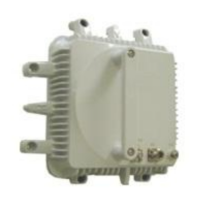
Figure 17. 13 GHz ODU attached directly to a 0.6m antenna. NHG type ODU; the IHG antenna interface is identical.
The antenna delivery includes two different O-rings. For direct mount, the larger O-ring has to be used. The
smaller one is for attaching a flexible waveguide in a separate installation. Both O-rings must not be used.
Figure 18 below depicts the antenna flange. The inner groove is for the PDR-flange (used for separate
installation). The larger outer groove is for the direct installation.
Figure 18. Flexible waveguide for separate installation uses the inner groove and smaller O-ring. Direct mount
installation uses the larger O-ring in the outer groove.
Groove for the large
O-ring for direct
mount installation
method.
O-ring (gasket) for the
IEC standard flange.
 Loading...