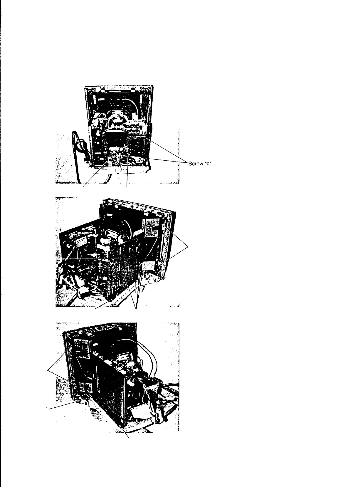
5. Disconnect the connectors “CN-J”,
“CN-L”,
“CN-C”, “CN-IN” and “CN-A”.
(from VIDEO PWB ASSY)
Disconnect the connectors “CN-B”,
“CN-HC”, “CN-R”, “CN-G” and
“CN-
M”.(from
CRT PWB ASSY)
Remove the three screws
“c”.
Remove the screw
“e”.
Remove the VIDEO PWB ASSY. (with
VIDEO BRACKET)
Screw
“c”
Screw
“e”
-
6.
Remove the four screws “c”.
Remove the two screws
“f”.
Remove the screw “k”.
Remove the BRACKET (L).
Screw “f”
Screw
“e
BRACKET
(L)
Screw
“k”
Screw
“c”
>
S
c
rew
“f”
7. Disconnect the connectors “CN-SW”,
“CN-Z”, “CN-D/C” and “CN-K”. (from
the SW REG UNIT)
Remove the screw
“f”.
Remove the screw
“k”.
Remove the two screws “d”.
Remove the SW REG BRACKET (R)
ASSY. (with SW REG UNIT)
Screw
“k”
8