5
2 System overview
SMART DEAC
Nedap Part.no. 9937676
Antenna
Model: SDA-265x265
Nedap Part.no.: 9564101
or
Model: DAPL-275x275
Nedap Part.no.: 9911537
Power Adapter
NedapPart.no.:9651802
LED
Nedap Part.no.: 9563652
Input
Output
RS485communication
1
7
6
5
2
4
3
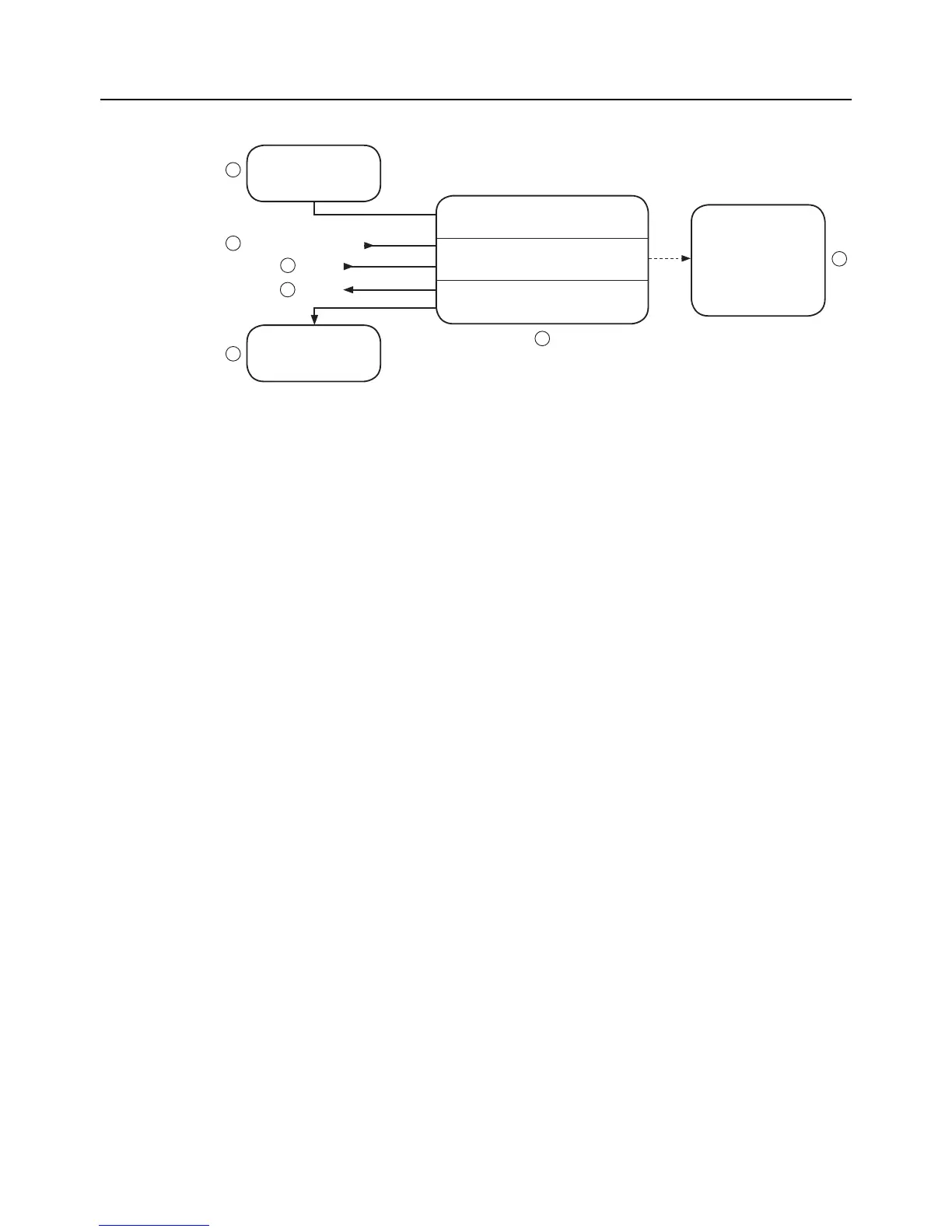
Figure 1 Functional system overview
The SMART DEAC system (Figure 1) consists of the following components:
1. AC/DCPoweradapterWallMount100–240VAC/12VDCNedapPart.no.:(9551802)
2. Smart Deactivator electronics (9937676)
3. Antenna including cable - Model: SDA-265x265 (9564101) or Model: DAPL-275x275 (9911537)
4. RS485connectiontocommunicatewiththeSMARTDEAC
5. Inputforfunctionalitytobedened
6. Outputforfunctionalitytobedened
7. LED for visual indication (9563652)
The SMART DEAC system is plug & play. You only have to follow the next steps:
• Install the Smart Deactivator system according the instructions;
• Power up the Smart Deactivator system;
• Check the functionality; by deactivating a RF label above the antenna and check it for a audio signal.
• Call Nedap EAS Support for quick hands-on problem solution in case of unforeseen trouble
(see Technical Support on page 2)