Section 5: Disassembly Guide
5- 3
Caution: Failure to unlock connector J3 on the CPU PCB before
attempting to remove the front panel flex circuit could damage the
flex circuit.
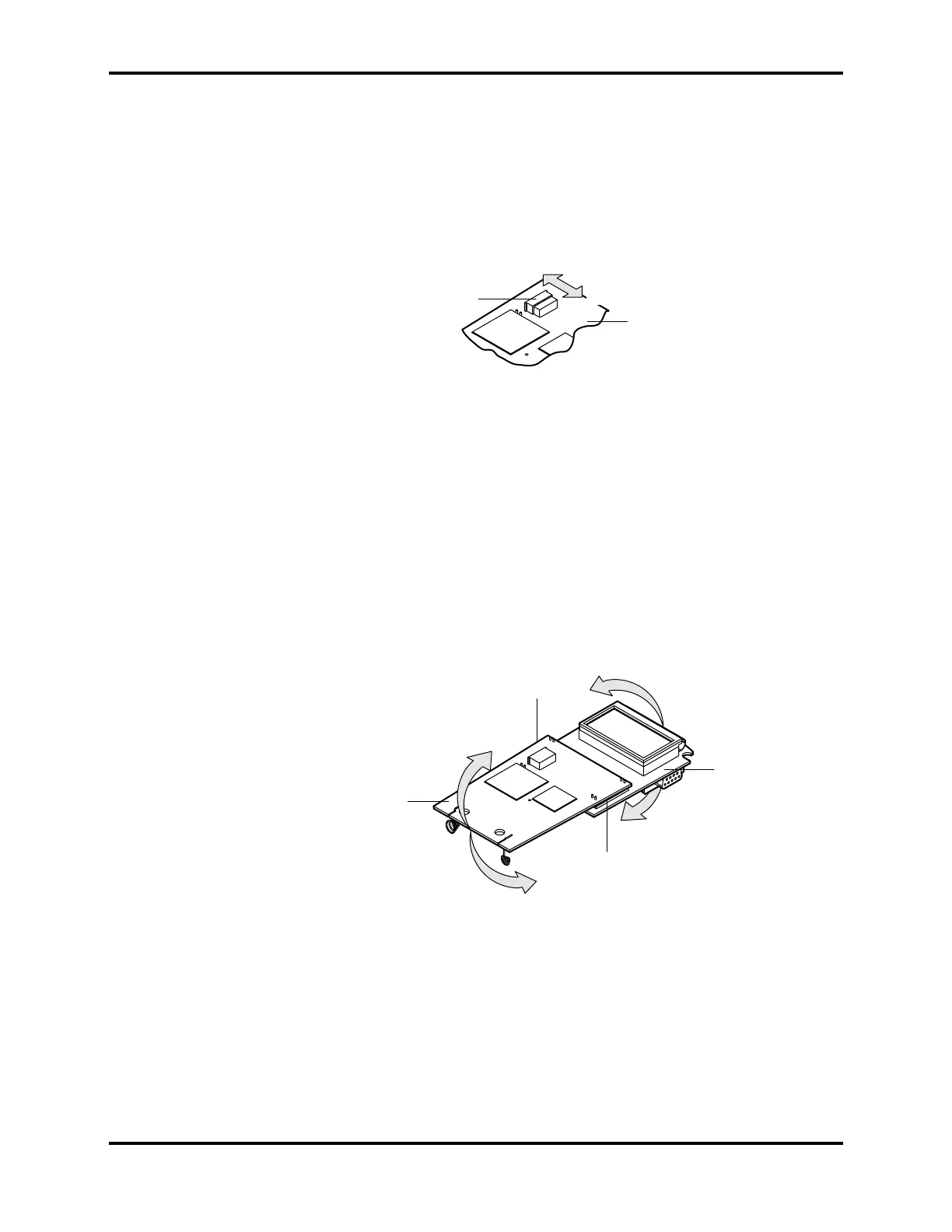
5. Unlock connector J3 on the CPU PCB as shown in Figure 5-3 and pull
the front panel keypad flex circuit out of J3.
Note: When reassembling the NPB-40, be sure to lock J3 after you
insert the front panel keypad flex circuit. See Figure 5-3.
J3 Lock
CPU PCB
Unlock
Lock
Figure 5-3: Unlocking CPU PCB Connector J3
Note: The battery connectors (spring assemblies) at the bottom of the
CPU PCB are held in slots in the battery compartment. In the
next step, observe how these connectors are engaged in these
slots when you remove the CPU PCB with the LCD PCB and
make sure the battery connectors are inserted back in these
slots when you reassemble the NPB-40.
6. Lift the CPU PCB and the LCD PCB together and remove them from
the case bottom.
7. To separate the CPU PCB and the LCD PCB, grasp the CPU PCB in
one hand and the LCD PCB in the other. Rotate the ends of the two
PCBs as shown in figure 5-4 until the two assemblies separate at the
connectors J1 and J2.
J2
J1
CPU PCB
LCD PCB
Figure 5-4: Separating LCD PCB from CPU PCB
Note: When reassembling the NPB-40, be sure to align all 20 pins of
both J1 and J2 on the CPU PCB with all 20 sockets of J1 and
J2 on the LCD PCB before pressing the two PCBs together.