Table of Contents
iv
LIST OF FIGURES
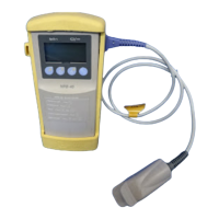
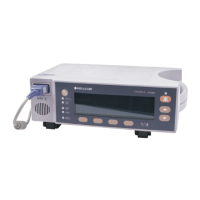
1-1 NPB-40 Handheld Pulse Oximeter ................................................ 1-1
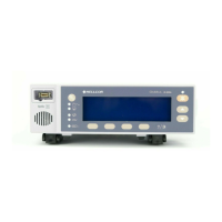
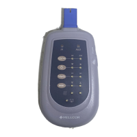
1-2 NPB-40 Front Panel....................................................................... 1-2
2-1 NPB-40 Battery Installation ........................................................... 2-2
3-1 NPB-40 Self-Test Front Panel Display .......................................... 3-1
3-2 Printer Interface Setup................................................................... 3-3
3-3 Typical Average Data Print Out ..................................................... 3-4
3-4 Typical Data Print Out ................................................................... 3-5
4-1 Typical Error Code Display ............................................................ 4-2
5-1 Opening the NPB-40 Case ............................................................ 5-2
5-2 Top Case Removal ........................................................................ 5-2
5-3 Unlocking CPU PCB Connector J3 ............................................... 5-3
5-4 Separating LCD PCB from CPU PCB............................................ 5-3
6-1 NPB-40 Expanded View ................................................................ 6-2
7-1 Repacking the NPB-40 .................................................................. 7-2
S2-1 Oxyhemoglobin Dissociation Curve .............................................. S-2
S3-1 NPB-40 Block Diagram ................................................................. S-4
S3-2 CPU PCB Block Diagram .............................................................. S-6
S3-3 LCD PCB Block Diagram............................................................... S-12
S4-1 CPU PCB Parts Locator Diagram.................................................. FO-1
S4-2 LCD PCB Parts Locator Diagram .................................................. FO-2
S4-3 CPU PCB Schematic Diagram ...................................................... FO-3
S4-4 LCD PCB Schematic Diagram....................................................... FO-4
S4-5 Front Panel Keypad Schematic Diagram ...................................... FO-5
LIST OF TABLES
4-1 Troubleshooting Guide .................................................................. 4-2
4-2 NPB-40 Error Codes ..................................................................... 4-5