Networkable VAV Controller
Specification and Installation Instructions
www.neptronic.com EVCB Standard Page | 12
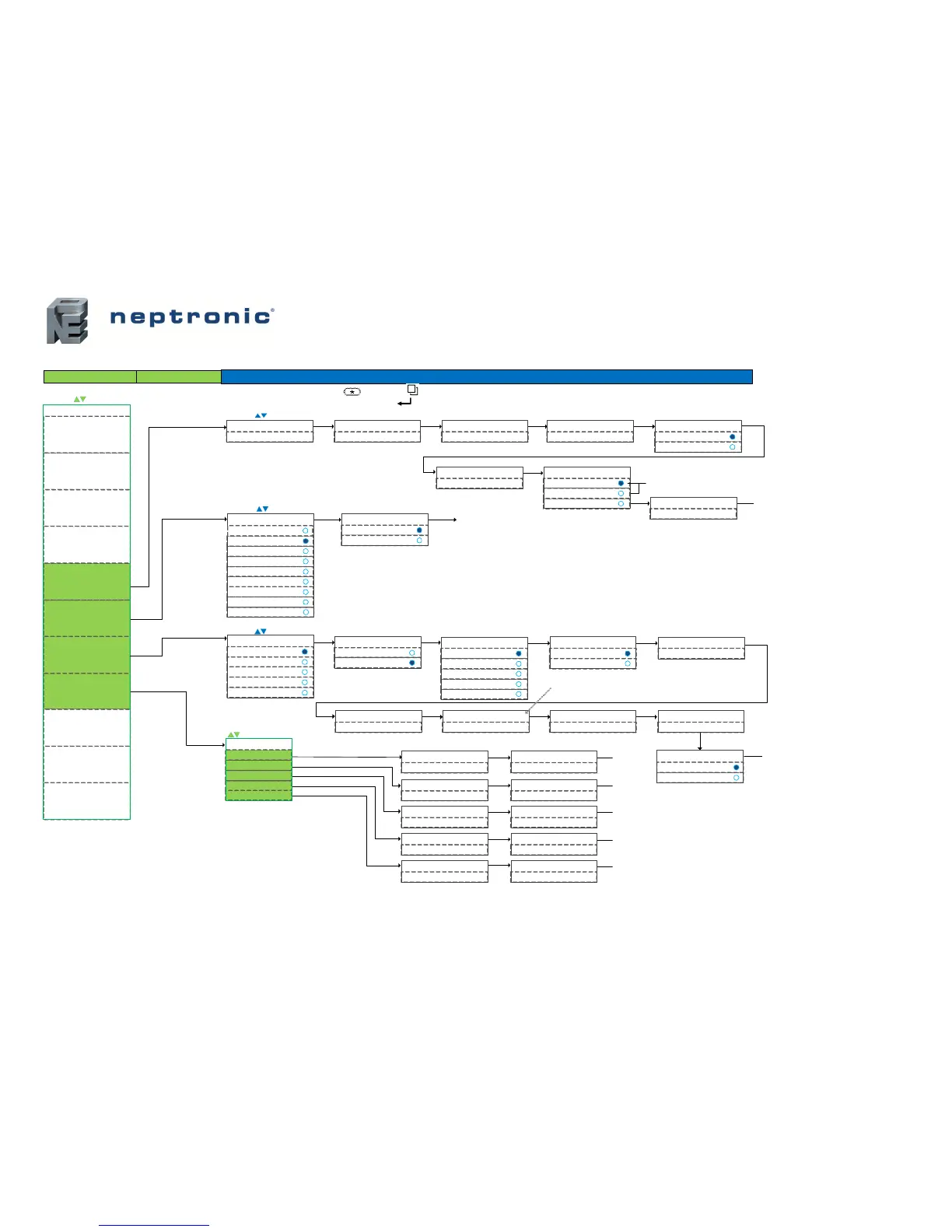
Settings – Menu (5 of 6) | Temp, Motor, Settings and Ramps
ANLg (analog 0-10Vdc)
Hr2 (heating ramp 2)
CLHt (auto/off)
Cor (changeover ramp)
CH1 (cool/heat)
OFF (no display: blank)
ON (manual heat/cool)
NEt (network)
Main Menu
= select / set value
Intern Temp Sensor Offset
Actualtemp°C/°F
Extern Temp Sensor Offset
Actualtemp°C/°F
User Minimum Setpnt
15.0°C/59°F
User Maximum Setpnt
30.0°C/86°F
User Setpnt Locked
No (unlocked)
Yes (locked )
User Setpnt
22.0°C/72°F
Temp Control Sensor
ItS (internal sensor)
EtS (external sensor)
Go to "mot"
Go to
"mot"
Network timeout Minutes
5 min (0-60 min)
(Av.16 – AV.17)
(AV.16-40°C / AV.16-104°F)(10 °C-AV.17 / 50° F-AV.17)
(± 5°C / ± 10°F)
Appears only if AI1 or AI2 = EtS
COOl (cool/off)
Temp Control Mode
Auto (automatic all modes)
HEAt (heat/off)
= select / set value
Enable onoff Control Mode
No (D isa bled)
Yes (Enabled)
StP (setpoint)
t°c (temp only)
Display Info
t°c (temp & demand)
StP (setpoint & demand)
Freeze Protect
No (D isabled )
Yes (Enabled)
Cooling anti cycle minutes
2min(0-15 min)
Cl Ht Switch Time in Minutes
0min(0 -120 m in)
Heating Intgral time in Sec
0sec(0-250 sec)
Cooling Intgral time in Sec
0sec(0-250 sec)
Go to
"rMp"
CH Over Prop Band
2.0°C/4.0°F(0.5-5°C / 1-9°F)
CH Over Dead Band
0.3°C/0.6°F(0-5°C / 0-9°F)
Hr1 (heating ramp 1)
Cr2 (cooling ramp 2)
Cr1 (cooling ramp 1)
Ramp Setting
COr (changeover)
= scroll menu items
CR1 Prop Band
2.0°C/4.0°F(0.5-5°C / 1-9°F)
CR1 Dead Band
0.3°C/0.6°F(0-5°C / 0-9°F)
CR2 Prop Band
2.0°C/4.0°F(0.5-5°C / 1-9°F)
CR2 Dead Band
0.3°C/0.6°F(0-5°C / 0-9°F)
Hr1 Prop Band
2.0°C/4.0°F(0.5-5°C / 1-9°F)
Hr1 Dead Band
0.3°C/0.6°F(0-5°C / 0-9°F)
Go to "Cr1"
Go to "Cr2"
Go to "Hr1"
Go to "Hr2"
Sub Menu Configuration
= scro ll m enu items
StFl (stpnt airflow 0-10Vdc)
Hr2 (heating ramp 2)
Hr1 (heating ramp 1)
Cr2 (cooling ramp 2)
Motor Signal Ramp
= select / set value
Motor DIR-REV
DIR (dire ct )
REV (reverse)
Airflow Intgral time in Min
0min(0-6 0 min)*
Hr2 Prop Band
2.0°C/4.0°F(0.5-5°C / 1-9°F)
Hr2 Dead Band
0.3°C/0.6°F(0-5°C / 0-9°F)
Go to "NEt"
Cr1 (cooling ramp 1)
EtS appears only if AI1 or AI2
is set to EtS
AV.10
(± 5°C / ± 10°F)
MSV.35
MSV.17
AV.11
BV.40
BV.3
AV.170
AV.56
AV.41
AV.46
AV.21
AV.24
AV.57
AV.42
AV.47
AV.22
AV.25
AV.16
AV.15
MSV.95
AV.106
AV.17
MSV.4
BV.6
AV.30 AV.50
AV.51
AV.145
BV.2
BV.100
OFF (follows NSB/NoOcc)
Fan Always On Mode
On (always on)
= For fan powered box applications and
available only with models:
- EVCB14NIT4S
- EVCB14NDT4S
- EVCB14NIT4SF
The analog or Triac output ramps must be set
to O n
On = Fan is always on (continuous).
Off = Fan is off if control mode is off or if there
is no demand when in NSB or No Occupancy
mode via digital input or schedule.
BV.100
* = Airflow integral is not functional on pressure
dependent model EVCB14NDT4S, ignore the option.
Go to "SEtc"
OFF~
OPt (Options)
Only available with CO
2
sensor models
Main Menu
APPS (Applications)
PrSs (Pressure)
rMp (Ramps)
NET (Networ k)
HrS (Time & Date)
Setc (Settings)
Mot (M otor)
tMp (Temperature)
OutP (Outputs)
InPt (Inputs)
*** To save any changes, press on TRL and on TDU ***
*** To the previous step without saving, press on TRL and TDU ***
 Loading...