Table 1. LEDs on the front panel (Continued)
DescriptionLED
Solid green. A valid 1 Gbps link is established.
Blinking green. The port is transmitting or receiving packets at 1 Gbps.
Solid amber. A valid 10 Mbps or 100 Mbps link is established.
Blinking amber. The port is transmitting or receiving packets at 10 Mbps or 100 Mbps.
Off. No link is established.
LAN LEDs
Link, speed, and
activity for Ethernet
ports 1 to 4
For future use.Rightmost LED
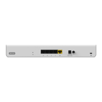
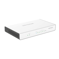
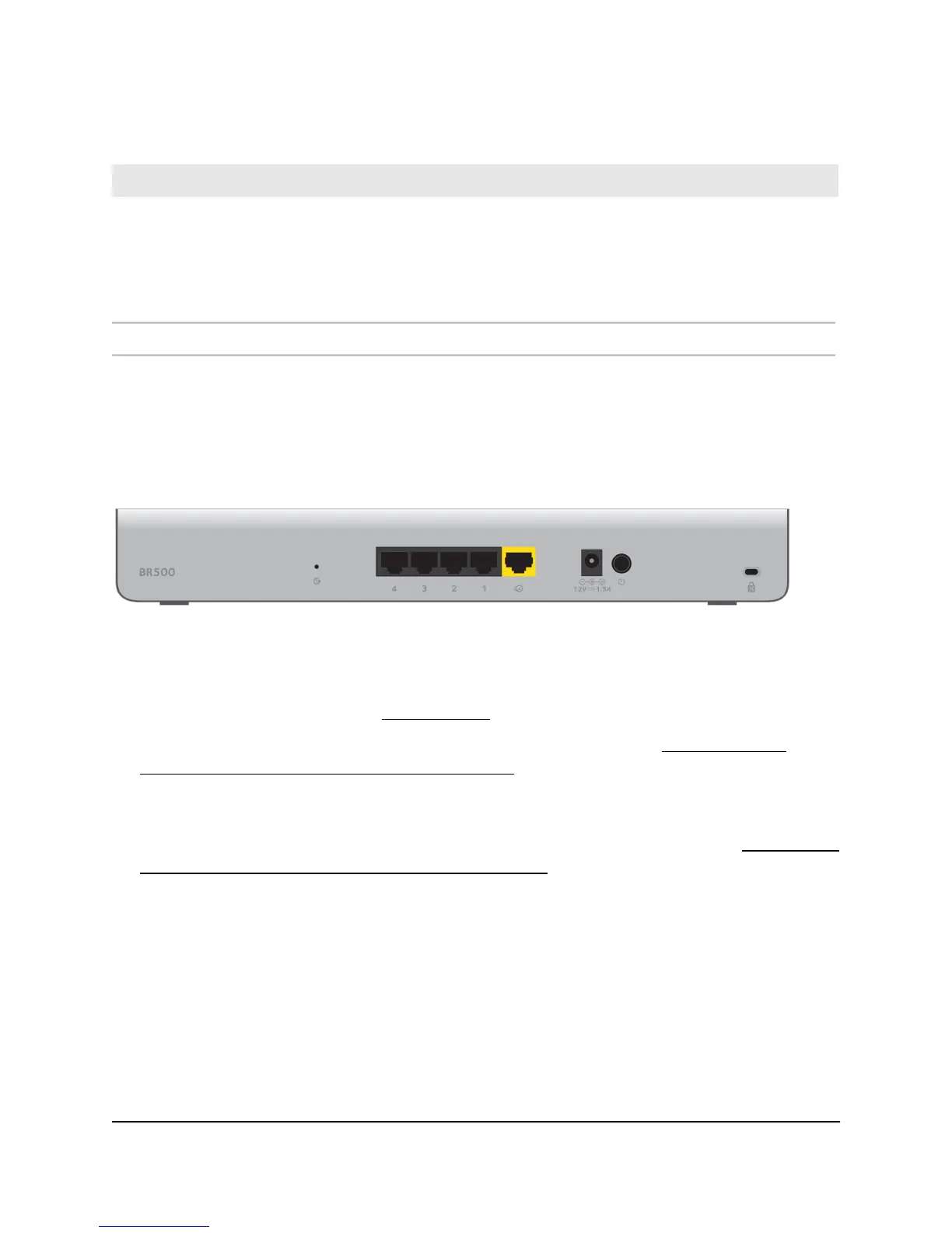
Back panel
The following figure shows the back panel.
Figure 2. Back panel
From left to right, the back panel contains the following components:
•
Recessed Reset button (see Reset button on page 12).
•
Four independent 10/100/1000BASE-T RJ-45 LAN ports (see RJ-45 ports for
10/100/1000M BASE-T Ethernet connectivity on page 12) for connections to devices
such as a switch, WiFi access point, ReadyNAS storage system, security camera, and
computer.
•
One independent 10/100/1000BASE-T RJ-45 WAN (Internet) port (see RJ-45 ports
for 10/100/1000M BASE-T Ethernet connectivity on page 12) for connection to an
uplink such as a cable or DSL modem.
•
DC power receptacle to be used with the power adapter that is provided with the
router.
•
On/Off power button.
•
Kensington lock for an optional security cable.
Hardware Installation Guide11Hardware Overview
Insight Instant VPN Router BR500
 Loading...