RF Planning and Deployment
90
ProSAFE Wireless Controller
9. To generate the heat map for the 5 GHz band, on the right, click the Band icon.
The heat map for the 5 GHz band is generated and displays. Use the color information on
the right as guidance for WiFi coverage.
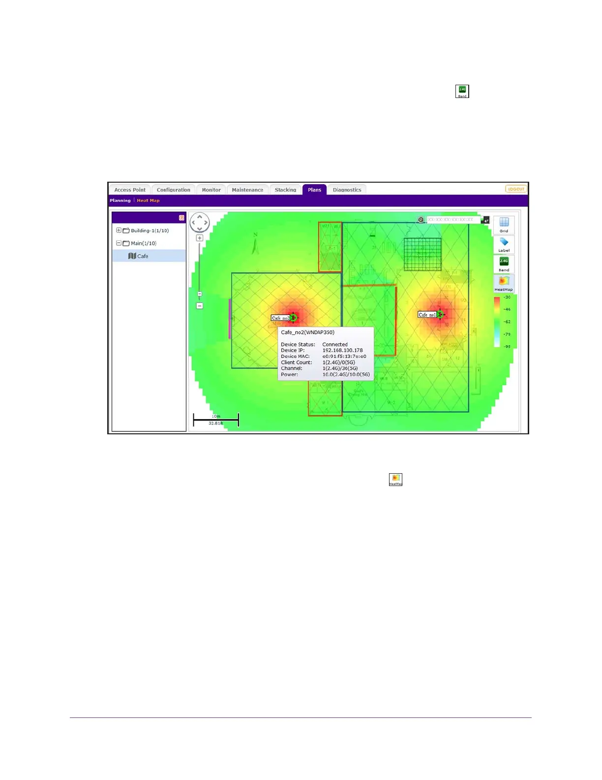
10. To see the information about an individual access point or antenna, point to the location.
A pop-up field displays the information.
.
11. To make adjustments to the WiFi coverage, drag the access points to new locations on the
floor map.
12. To regenerate the heat map, on the right, click the HeatMap icon.
The heat map is generated and displays. Use the color information on the right of the heat
map as guidance for WiFi coverage.
13. If you made changes to the WiFi coverage on the floor map in Step 11, move each physical
access point to the actual physical location on the floor that matches the virtual location of
the virtual access point on the floor map as closely as possible.
In other words, reverse the process that you accomplished in Step 7 and now make sure
that the actual placement on the floor matches the virtual placement on the floor map.
 Loading...