6. Slide the Sled Stop Latch between the Sled Stop and the BNB on the input
side of the printer. Attach it to the Sled Stop Member using the two
Philips flat head screws removed earlier.
7. Plug in the three FFCs from the BNB to the Main PCA. Carefully align the
black cable in the connector and close the lock. Misalignment will
damage the cable and require replacement of the BNB and will void the
warranty.
8. Remove all the orange packing material.
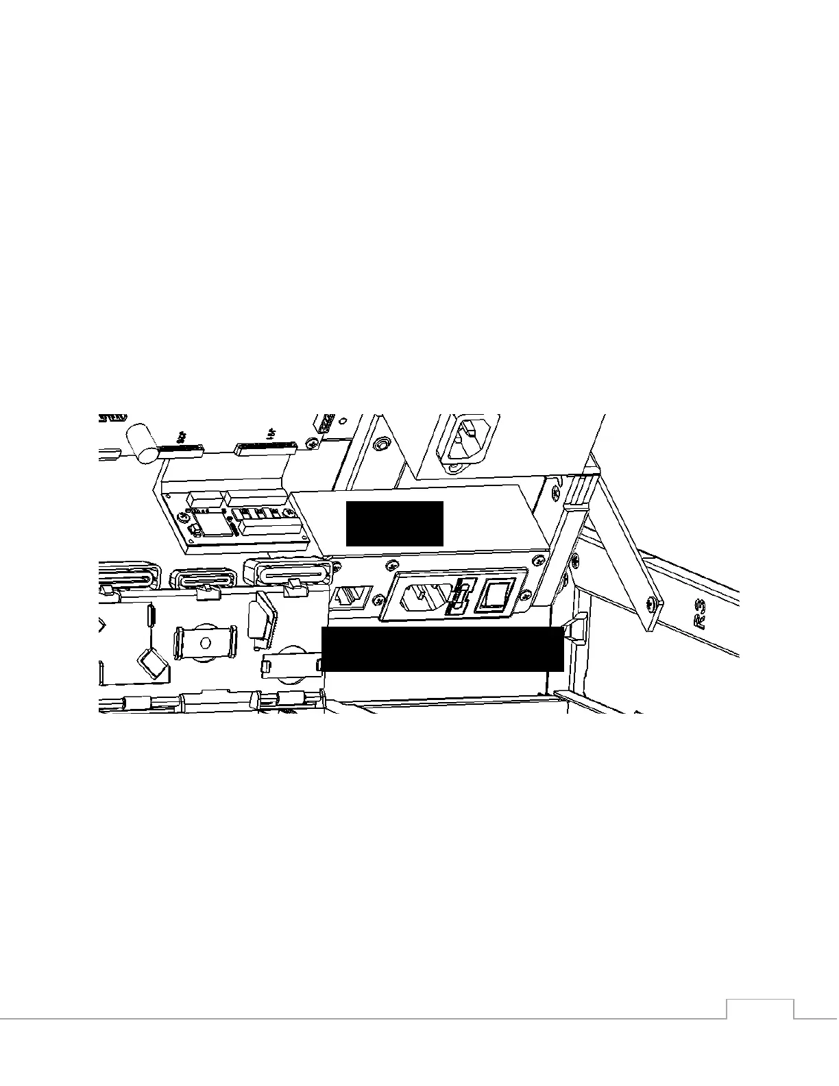
9. Locate the Ethernet, AC Power, and Power Switch on the power brick.
When the electronics tray is in the upright position, the power brick will
be facing inwards on the right side of the printer.
10. Plug in AC Power and Ethernet to the printer. Do not power on yet.
 Loading...
