6 www.neutonpower.com
Washe
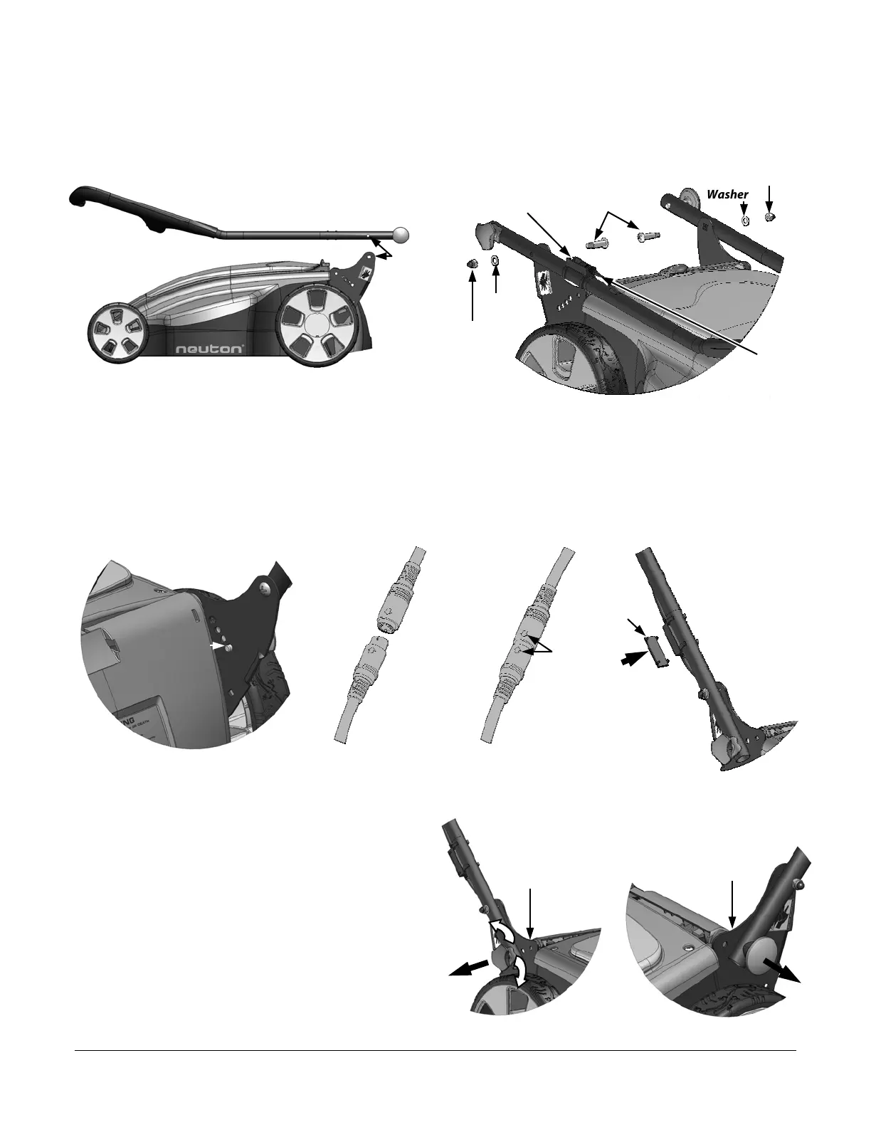
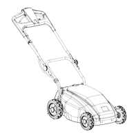
Step 3: Attach and Adjust the Handlebar.
1. Remove either one of the Wrenches from under the Access Cover and close the Cover (Figure 2 on page 5).
2. Lay the Handlebar on top of the Mower and align the two (2) holes as shown in Figure 3.
3. Insert a 8mm x 38mm Shoulder Bolt from the inside through the aligned holes (Figure 4), attach a 8mm Lock Nut and
repeat for other side. Tighten the Lock Nuts using the small Hexagonal end of the Wrench and a Phillips Screwdriver.
4. Rotate the Handlebar into the upright position. The Handlebar will lock into its highest position producing an audible
click. Note the Silver Pin protruding through the hole in the Steel Plate (Figure 5).
5. Unsnap the Handlebar Cable from the Main Cable Holder (Figure 4).
6. Locate the opposite end of the Main Cable from the Mower (Figure 6a), line up the raised Arrows (Figure 6b) on each
connector, and push the connectors together until fully mated (Figure 6b).
7. Snap the mated connectors into the Main Cable Holder on the Handlebar (Figure 6c) and then snap the Protective Cover
over the mated connectors.
8. To adjust the Handlebar height, pull the right Knob
(Figure 7) all the way out and twist the Knob in either
direction 1/4 turn. This will lock the Knob in the out
position.
9. While holding the Handlebar, pull the left Knob (Figure 8)
all the way out and rotate the Handlebar to the desired
position. Release the Knob and move the Handlebar until
the Knob clicks back into position with an audible “click”.
Make sure the Silver Pin is protruding through one of the
four (4) Height Adjustment holes in the Steel Plate.
10. Slowly twist the right Knob until it locks into position with
an audible “click”. Check to make sure both Silver Pins are
protruding though their respective holes in the Steel
Plates.
Figure 3 Figure 4
Holes
aligned
8mm x 38mm
Shoulder Bolts
8mm Lock Nu
Figure 5
Steel
Plate
Silver Pin
Main Cable Holder
Handlebar
Cable
Female End
Male End
Figure 6a
Raised
Arrows
Figure 6c
Push to
snap in
place.
Figure
Figure 8
Steel Plate
Steel Plate
Protective
Cover
Figure 6b
Washe