4081 User Manual Issue 3
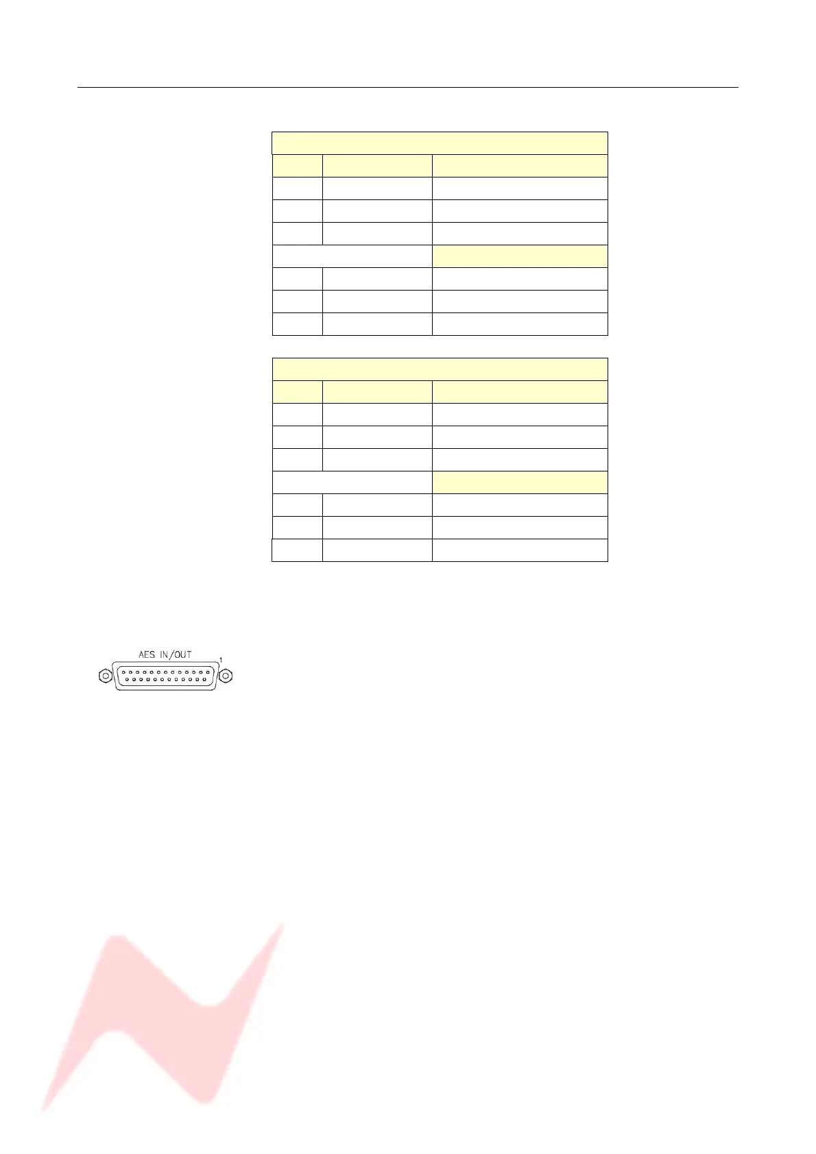
AES INs / OUTs
These signals are on a 25-way D-sub connector.
AES RECEIVE
Pin Signal name Female XLR 1 pin:
12 AES RX 1+ 2
24 AES RX 1- 3
25 screen 1
Female XLR 2 pin:
23 AES RX 2+ 2
10 AES RX 2- 3
11 screen 1
AES TRANSMIT
Pin Signal name Male XLR 1 pin:
6AES TX 1+ 2
18 AES TX 1- 3
19 screen 1
Male XLR 2 pin:
17 AES TX 2+ 2
4AES TX 2- 3
1screen 1
• AES 1 contains data for channels 1 (L) and 2 (R) from the 4081
• AES 2 contains data for channels 3 (L) and 4 (R) from the 4081
On the AES Ins/Outs 25-way connector on the rear of the 4081, a
number '1' printed next to the corner of the connector indicates the
location of Pin 1.
NB:
Please note that analogue breakout cables will not be suitable for use
with this connector.
Ensure you use a cable wired to the Tascam AES convention instead.
(An analogue cable is wired pin-to-pin, an AES cable has the pins crossed
so pin 1 goes to pin 25 etc).
- 26 -