QUICK REFERENCE CARD – NEW HOLLAND CX COMBINES
Form 147074 Rev. E (E27025) Page 2 of 4
873 Adapter Initial Settings
(continued)
Set the center link between the header and
adapter to 19-1/4” (490 mm) length (pin to
pin).
Set the float to specs given on pages 3 & 4.
Set the draper speed flow control so number
“4” is at the 12 o’clock position.
Header Initial Settings
See page 4 for 963 Header
For 973/974/84C Model Headers: Set the
center delivery opening to 55.5” (1410 mm).
Position the decks so there is equal
overlap of adapter feed draper each
side.
Align the vertical edge of the rear deflectors
on the feed pan just inside the edge of the
feeder house opening to ensure smooth
crop flow.
Re-check skid plate clearance (set during
873 initial settings) with adapter inserted in
header. (see appropriate dimensions below)
Refer to 873 Operator’s Manual for further
details.
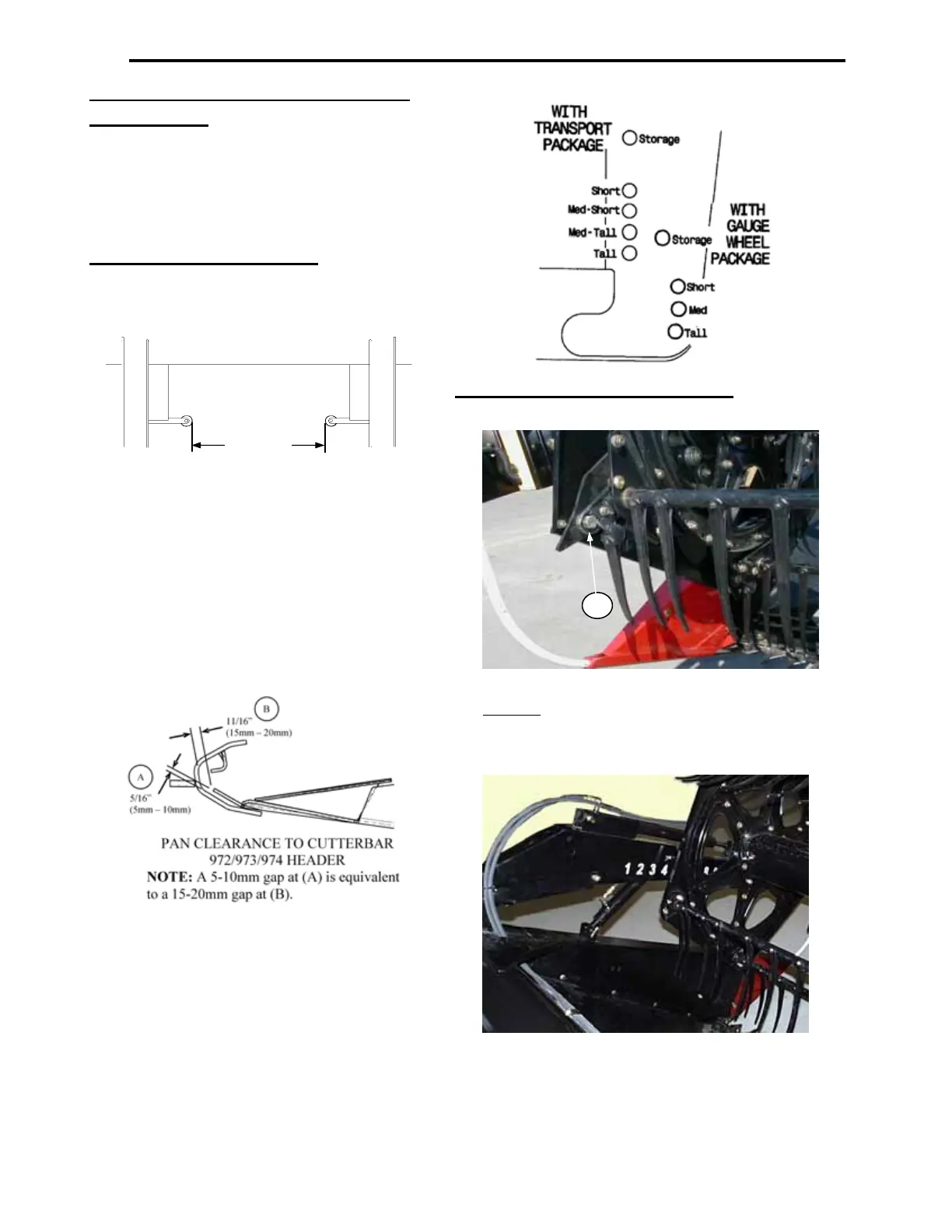
Gauge wheels are intended to help float the
header when cutting off the ground. For
such applications set gauge wheels in the
Short – Tall setting depending on cut height.
Note: When cutting on the ground place
gauge wheels in the storage position.
Pickup Reel Initial Settings
See page 4 for 963 Header
Install bolt (C) through the cam arm with head
inboard
and torque to 120 ft. lbs. (162 N·m.)
Adjust the finger pitch to position 5.
Set the fore/aft position to between 4 and 5 on
the gauge decal at left reel support arms.
Reel finger to sickle guard minimum clearance with
reel fully lowered is 5/8” (15mm), measured at
both ends of the cutterbar for 973 headers. For
974/84C headers, flex to full frown when
checking clearance at hinge points.
Recommended reel speed is 10% above ground
speed.
C
55.5”
1410 mm
973/974/84C
 Loading...