INSTALLATION RECOMMENDATIONS
(see example below)
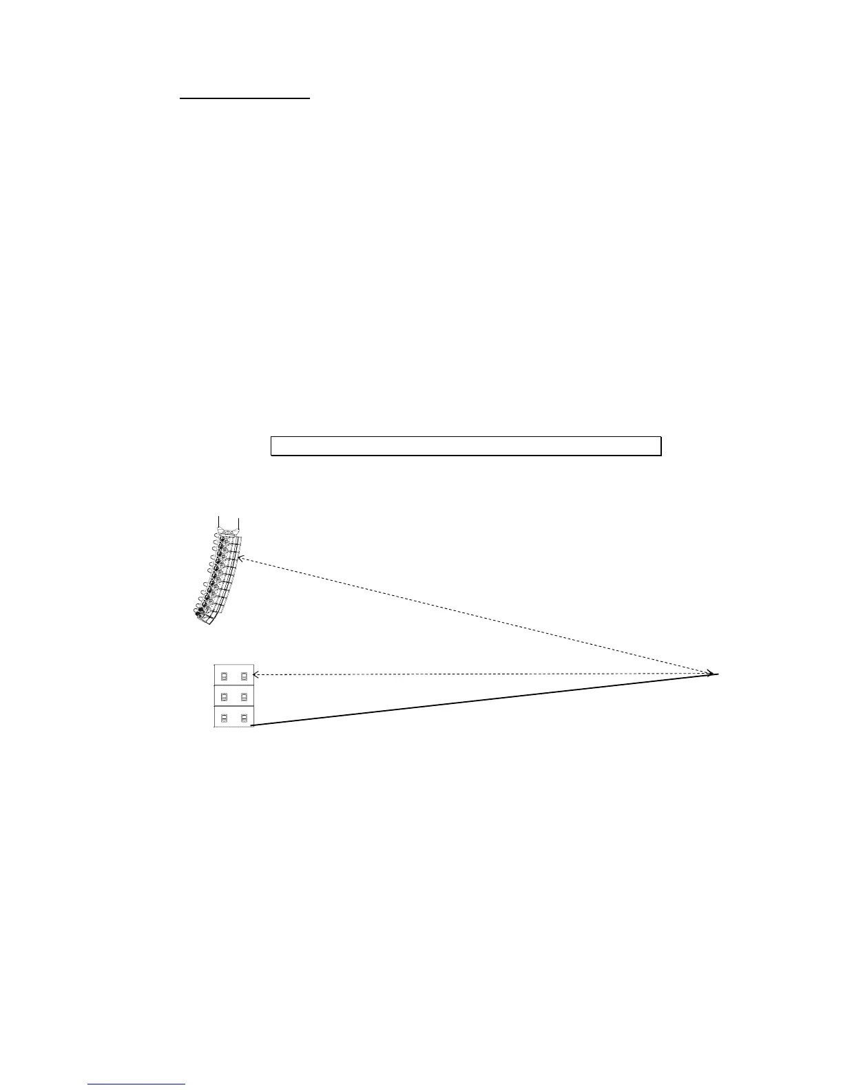
We recommend that the system is adjusted so that arrivals from MAIN SYSTEM array and
SUB speakers are coincident at a fairly distant listening position (typically further than the
mixing position).
Geometrical alignment
In the example below, r
1
being the smaller distance from MAIN SYSTEM array to listener
position, and r
2
being the smaller distance from SUB to listener position, the distance
difference is then r
1
–r
2
(specified meters or feet).
• r
1
> r
2
, the delay should be set on the SUB NXAMP Powered TDcontroller(s).
• r
1
< r
2
, the delay should be set on the MAIN SYSTEM NXAMP Powered
TDcontroller(s)
To convert the result in time delay (specified in seconds), apply:
∆t = (r
1
-r
2
)/C r
1
and r
2
in meters, C (sound speed) ≈ 343 m/S.
The delay parameter is set in MENU “Delay” (See above).
However, it is a safe practice to double-check geometrical alignment with a proper
acoustical measurement tool.
Measuring and aligning phase in the overlapping region
Microphone must be set on the ground, at a fairly distant listening position (typically
further than the mixing position).
Phase must be measured with a wrapped display, and measurement must be properly
windowed on signal arriving time (same window for SUB and MAIN SYSTEM). When
measurement is synchronized to the system-microphone distance, phase can be clearly