Page 40/58 RAY SUBS IMPLEMENTATION
t
θ
t
θ
t
θ
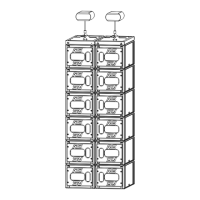
GROUP OF 2 RS15S STEERING GROUP OF 3 RS15S STEERING GROUP OF 4 RS15S STEERING
“Steering” delays values for the pairs can easily be computed according to following formula:
τ = h*sin(θ)/C (metric)
τ is the value to be applied to the second pair
h is the height of tilted elements ( 0.91m for 2 RS15s, 1.365m for 3 RS15s, 1.82m for 4 RS15s)
C is the speed of sound ( = 343m/s )
8.3.2 Delay values implementation
• If the coverage is to be tilted down, then top group delay should be set at 0ms and delay should
progressively increase on lower groups.
• If the coverage is to be tilted up, then lower group delay should be set at 0ms and delay should
progressively increase on upper pairs.
• Delay value for first group is always 0ms.
• Delay value for second group is τ
• Delay values for subsequent groups are 2τ, 3τ etc…
Table below lists these values for typical angle values:
TILT ANGLE 0° 5° 10° 15° 20° 25° 30° 35° 40° 45°
DELAY τ (ms)
0.0 0.2 0.5 0.7 0.9 1.1 1.3 1.5 1.7 1.9
GROUP
2 RS15s
DISTANCE (cm) 0.0 7.9 15.8 23.6 31.1 38.5 45.5 52.2 58.5 64.3
DELAY τ (ms)
0.0 0.3 0.7 1.0 1.4 1.7 2.0 2.3 2.6 2.8
GROUP
3 RS15s
DISTANCE (cm) 0.0 11.9 23.7 35.3 46.7 57.7 68.3 78.3 87.7 96.5
DELAY τ (ms)
0.0 0.5 0.9 1.4 1.8 2.2 2.7 3.0 3.4 3.8
GROUP
4 RS15s
DISTANCE (cm) 0.0 15.9 31.6 47.1 62.2 76.9 91.0 104.4 117.0 128.7
 Loading...