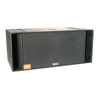
Page 14/58 RS15 GENERAL INSTRUCTIONS
2.3 Speaker connection
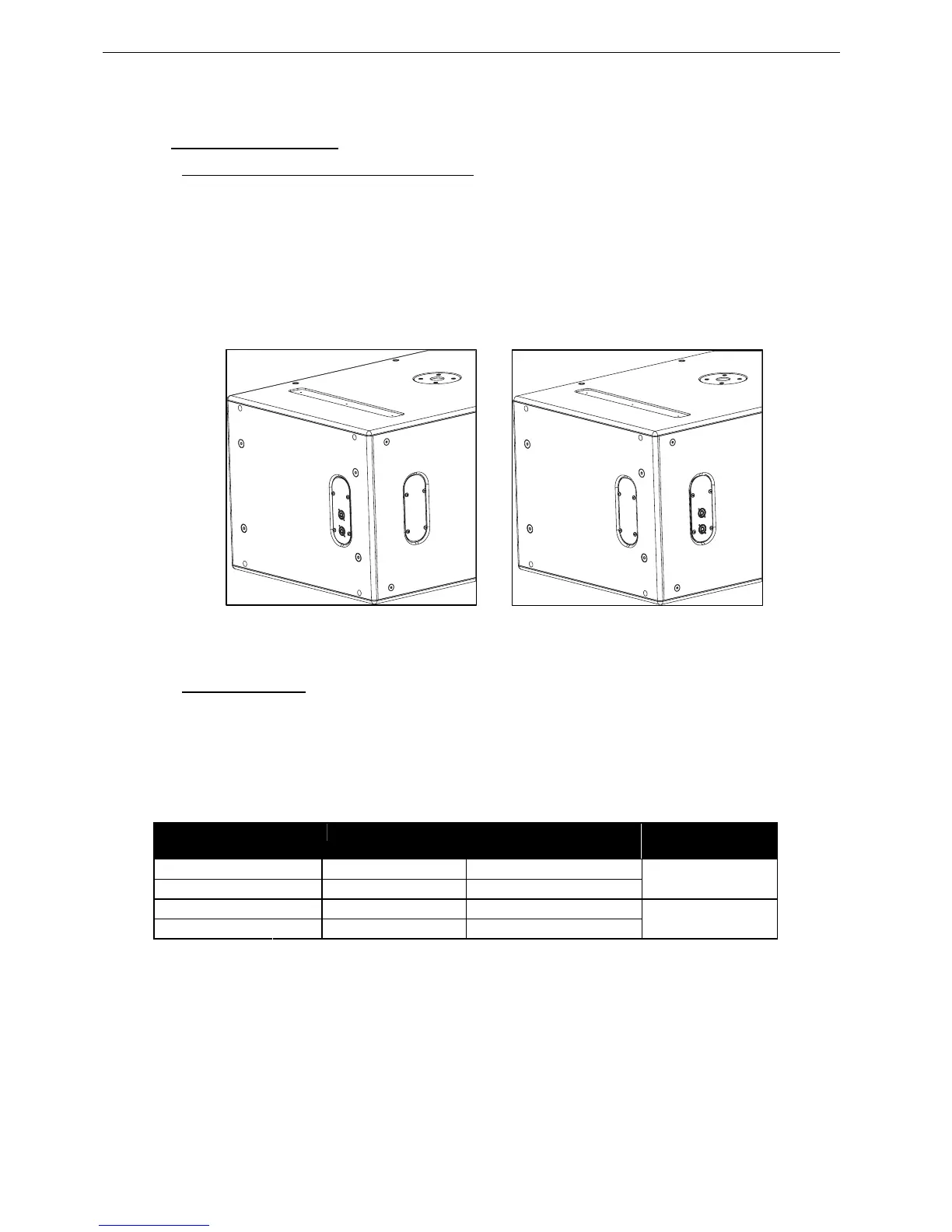
2.3.1 Configuring Connector and Owner plates
Owner and Connector plates can be exchanged depending on chosen directional configuration
Please note that the connector plate can pass through the holes, no unsoldering is therefore required.
• Directional Mode : it is recommended to install the connector panel on the side which supports
the rigging plates;
• Omni Mode: it is recommended to install the connector panel on the side opposite to the drivers
(factory default configuration)
CONNECTOR PLATE IN DIRECTIONAL MODE CONNECTOR PLATE IN OMNI MODE
2.3.2 RS15 connectors
RS15 is connected through Speakon NL4FC plugs (not supplied). A wiring diagram is printed on the
connection panel located on the back of each cabinet.
The 4 pins of the 2 Speakon sockets are connected in parallel within the enclosure.
Either connector can be used to connect an amplifier or to link to an additional RS15 cabinet.
Connectors are wired as follows:
Speakon NL4F
Connectors
Omni Mode Directional Mode Comment
1(-)
⇒
15’’ driver Right (-) 15’’ driver Rear (-)
1(+)
⇒
15’’ driver Right (+) 15’’ driver Rear (+)
Driver Next to Connector
Panel
2(-)
⇒
15’’ driver Left (-) 15’’ driver Front (-)
2(+)
⇒
15’’ driver Left (+) 15’’ driver Front (+)
Driver Opposite to
Connector Panel
 Loading...