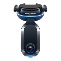
POWERED MOUNT
08
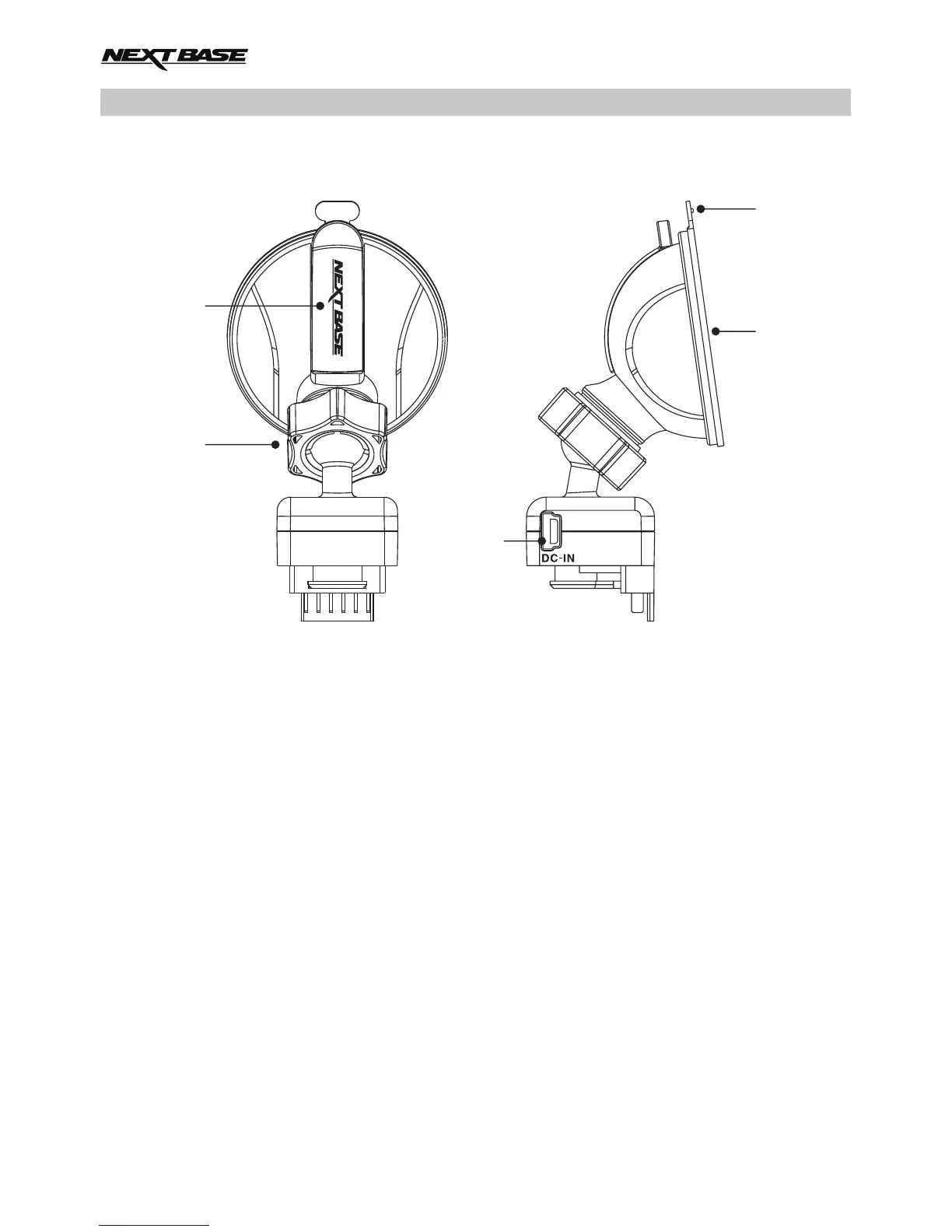
Please see below to identify the parts of the supplied powered mount.
1. Locking lever
The locking lever is used to attach and release the window mount to your vehicles windscreen.
Pull the lever down to prepare the window mount for use. Once the mount is firmly upon the
windscreen (in a suitable location) push the lever to lock the mount in place.
2. Locking ring
Loosen the locking ring to adjust the iN-CAR CAM position if required, remembering to
re-tighten before use.
3. DC-IN socket
Connect the supplied car power cable here.
4. Suction cup
This is used to attach and release the window mount to your vehicles windscreen.
Affix to a clear piece of windscreen where there is no paint effect applied.
5. Suction release tab
Once the locking lever has been opened use this release tab to break the seal between
the mount and windscreen.
4
5
1
3
2