General
The cooling system is connected to the heat pump collect-
or circuit, through which cooling is supplied from the
collector via the circulation pump and the shunt valve.
When cooling is required (activated from the outdoor
sensor and any room sensor) the circulation pump is ac-
tivated. The shunt valve regulates so that the cooling
sensor reaches the current set point value that is equal
to the outdoor temperature and the set min. value for
the cooling temperature (to prevent condensation).
Caution
This accessory may require a program software
update in your F1345.
2755 or higher is the minimum software version
for the heat pump.
Pipe connections
General
Pipes and other cold surfaces must be insulated with dif-
fusion-proof material to prevent condensation. Where
the cooling demand is high, fan convectors with drip trays
and drain connection are needed.
The brine circuit must be supplied with a pressure expan-
sion vessel. If there is already a level vessel installed this
should be replaced.
Non-return valve
Install a check valve between two T-pipe connections to
passive cooling on brine out (see the outline diagram).
Shunt valve
The shunt valve (QN18) is located in the brine system on
the flow line from the heat pump via the T-pipe connec-
tions according to the outline diagram.
A
B
AB
႑
Connect the brine out from the heat
pump via T-pipes to port A on the
shunt valve (opens at increased signal).
႑
Connect the flow line to the convector
fan from the shunt valve to the com-
mon port AB (always open)
႑
Connect the return line from the fan convector to the
shunt valve and brine out to the collector to port B via
T-pipe (closes at reduced signal).
Circulation pump
Install the extra circulation pump (GP13) after the shunt
valve (QN18) on the flow line to the fan convector.
Temperature sensor
႑
Install the flow temperature sensor for the cooling sys-
tem (BT64) on the pipe after the circulation pump
(GP13) in the direction of flow.
႑
Install the return line sensor for the cooling system
(BT65) on the pipe from the cooling system.
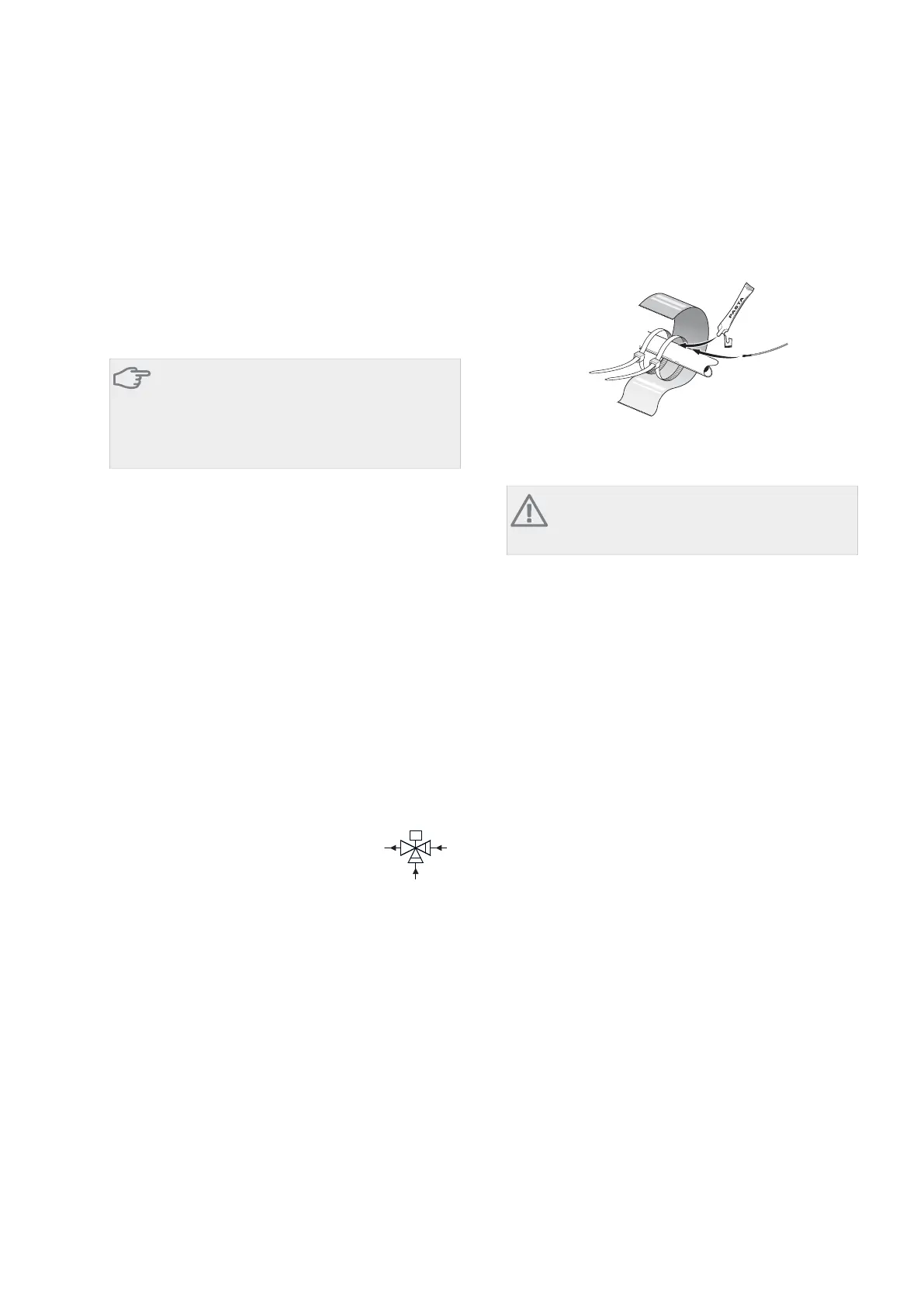
Install the temperature sensors with cable ties with the
heat conducting paste and aluminium tape. Then insulate
with supplied insulation tape.
NOTE
Sensor and communication cables must not be
placed near power cables.
AXC 50Chapter 8 | Passive cooling (4-pipe)28
8 Passive cooling (4-pipe)


 To Next Page