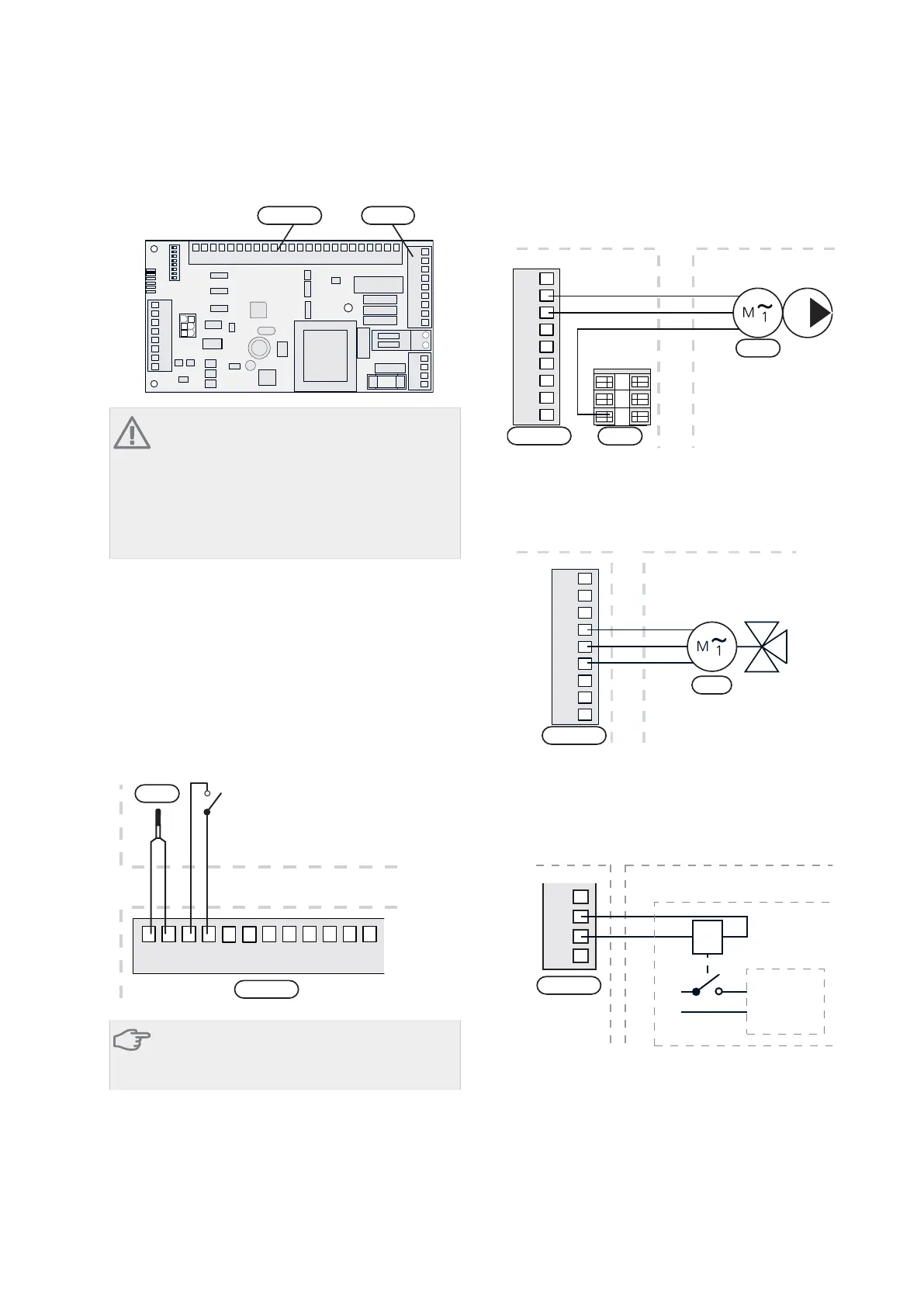
Electrical connection
ON
12345678
-X9
-X2
24 20212223 1516171819 1011121314 567891
1
N
L
PE
PE
1
2
3
4
5
6
7
8
2
3
4
5
6
7
8
9
234
-X8
-X4
-X10
-X1
$$; $$;
NOTE
All electrical connections must be carried out by
an authorised electrician.
Electrical installation and wiring must be carried
out in accordance with the stipulations in force.
F1345 must not be powered when installing
AXC 50.
Connection of sensors and external blocking
Use cable type LiYY, EKKX or similar.
Boiler sensor (BT52)
Connect the boiler sensor to AA5-X2:23-24.
External blocking (optional)
A contact (NO) can be connected to AA5-X2:21-22 to
block the addition. When the contact closes, the addition
is blocked.
24 20212223 1516171819 1314
%7
$$;
([WHUQDO
8QLW ER[
([WHUQDO EORFNLQJ
Caution
The relay outputs on the accessory card can have
a max load of 2 A (230 V) in total.
Connection of the circulation pump (GP10)
Connect the circulation pump (GP10) to AA5-X9:8 (230
V), AA5-X9:7 (N) and X1:3 (PE).
1
2
3
4
5
6
7
8
9
L
N
PE
3
2
1
8QLW ER[ ([WHUQDO
*3
$$;
;
Connection of the mixing valve motor (QN11)
Connect the mixing valve motor (QN11) to AA5-X9:6
(230 V, open), AA5-X9:5 (N) and AA5-X9:4 (230 V, close).
1
2
3
4
5
6
7
8
9
8QLW ER[ ([WHUQDO
41
1
6+
6+
&ORVH
2SHQ
$$;
Connection of the auxiliary relay for addition-
al heating
Connect the auxiliary relay for switching the addition on
and off to AA5-X9:2 (230 V) and AA5-X9:3 (N).
1
2
3
4
L
N
A1 A2
External auxiliary relay
Additional
Heating
8QLW ER[ ([WHUQDO
([WHUQDO DX[LOLDU\ UHOD\
$GGLWLRQDO
KHDW
$$;
AXC 50Chapter 3 | Shunt controlled additional heat6