General
The heating/cooling modes are controlled by 4 three-way
valves, which, depending on the outdoor temperature
and/or room temperature, switch between the different
modes.
The cooling supply to the building is controlled by the
set curve in the control system. After adjustment the
correct amount of cooling for the current outdoor tem-
perature is supplied. The flow temperature from the
three-way valves will hover around the theoretical re-
quired value (settable in the control system). In the event
of excess temperature F1345 calculates a surplus in the
form of degrees-minutes, which means that the greater
the excess temperature that temporarily prevails the more
the connection of cooling production is accelerated.
F1345 automatically switches to cooling mode when the
outdoor temperature exceeds the set value.
Passive cooling means that F1345 with the aid of the
circulation pumps, circulates fluid from the ground/rock
collector through the building's distribution system and
cools the building.
When the cooling requirement is large and passive cooling
is not sufficient, active cooling is engaged at the preset
limit value. A compressor then starts and the resulting
cold medium circulates to the building's climate system
and the heat circulates out to the ground/rock collector.
If several compressors are available these will start with
a difference of the set degree minutes.
NOTE
This system solution means that the brine will
also circulate through the heating system.
Check that all component parts are designed
for the brine in question.
Caution
This accessory may require a program software
update in your F1345.
2755 or higher is the minimum software version
for the heat pump.
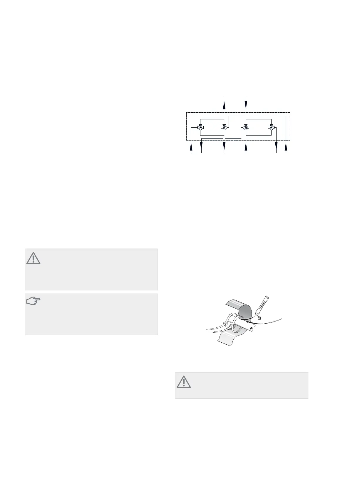
Pipe connections
Reversing valves
-EQ1
-QN13
-QN15
-QN14
-QN16
AB
B
A
AB AB
AA
BB
AB
Köldbärare
Kollektor
Köldbärare
Värmepump
Värmebärare
Värmepump
B
A
&OLPDWH V\VWHP
%ULQH KHDW SXPS%ULQH FROOHFWRU +HDWLQJ PHGLXP
KHDW SXPS
Install the three-way valves according to the outline dia-
gram above.
A: Open at signal.
B: Normally open (motor in standby mode).
AB: Always open.
Condensation insulation
Pipes and other cold surfaces must be insulated with dif-
fusion-proof material to prevent condensation.
Where the system may be operated at low temperatures,
any convection fan used must be fitted with a drip tray
and drain connection.
Temperature sensor
႑
External flow temperature sensor (BT25, connected in
F1345) must be installed on the flow line to the climate
system, after the three way valves (QN13) - (QN16).
Install the temperature sensors with cable ties with the
heat conducting paste and aluminium tape. Then insulate
with supplied insulation tape.
NOTE
Sensor and communication cables must not be
placed near power cables.
39Chapter 10 | Passive/active cooling (2-pipe)AXC 50
10 Passive/active cooling (2-pipe)