NOTE
All electrical connections must be carried out by
an authorised electrician.
Electrical installation and wiring must be carried
out in accordance with the stipulations in force.
The heat pump must not be powered when in-
stalling AXC 50.
Electrical circuit diagrams are at the end of the chapter
for each connection option.
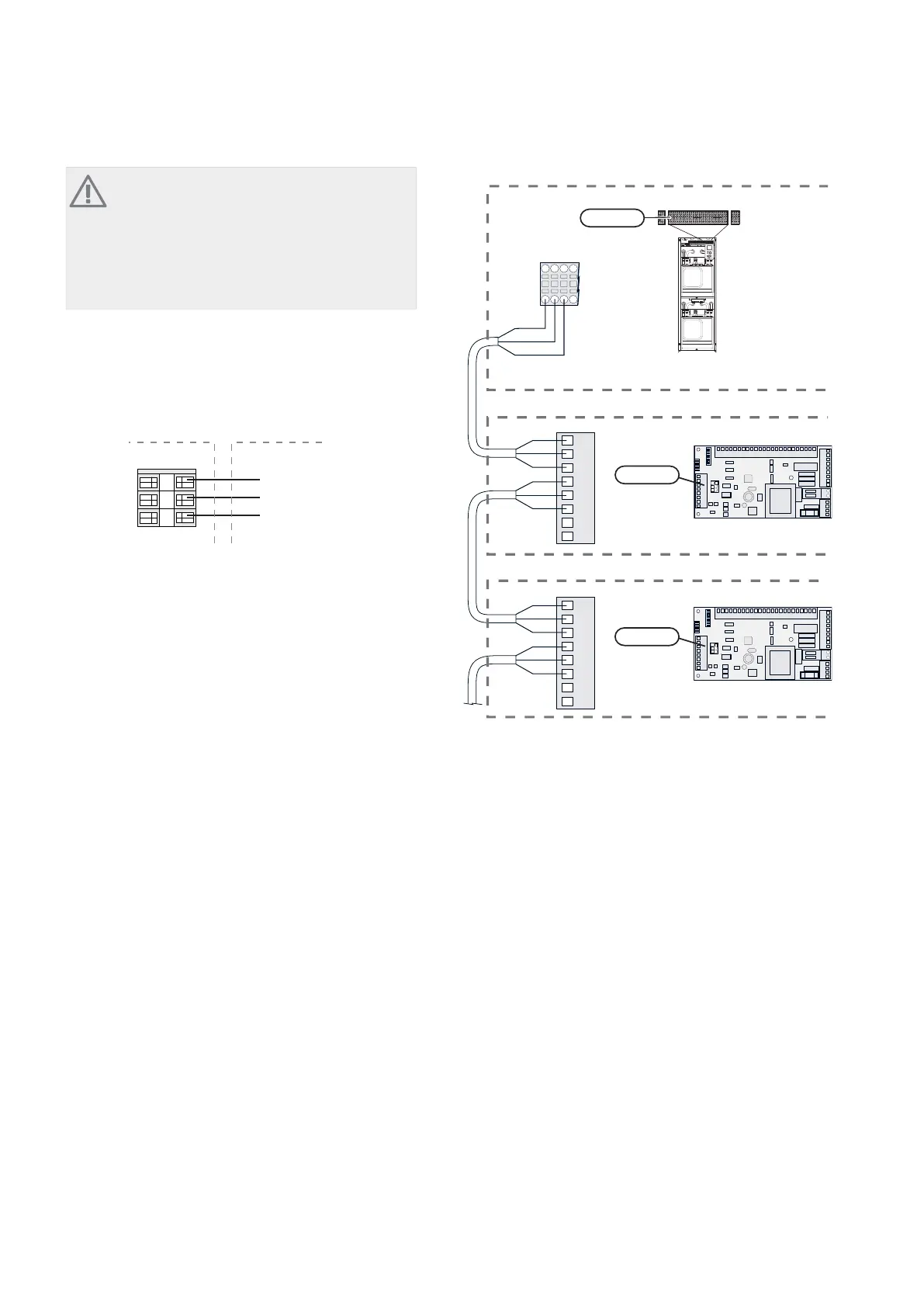
Connecting the supply
Connect the power supply to terminal block X1 as illus-
trated.
3
2
1
N
230V 50Hz-X1
L
PE
8QLW ER[ ([WHUQDO
Connecting communication
This accessory contains an accessories card (AA5) that
must be connected directly to the heat pump on terminal
block X6 in F1345.
If several accessories are to be connected or are already
installed, the following instructions must be followed.
The first accessory card must be connected directly to the
terminal block X6 in F1345. The following cards must be
connected in series with the previous card.
Use cable type LiYY, EKKX or similar.
1
2
3
4
5
6
7
8
AA5-X4
A
B
GND
A
B
GND
A
B
GND
A
B
GND
1
2
3
4
5
6
7
8
AA5-X4
X6
1234
A
B
GND
$FFHVVRU\ FDUG
$FFHVVRU\ FDUG
ON
12345678
-X9
-X2
24 20212223 1516171819 1011121314 567891
1
N
L
PE
PE
1
2
3
4
5
6
7
8
2
3
4
5
6
7
8
9
234
-X8
-X4
-X10
-X1
$$;
ON
12345678
-X9
-X2
24 20212223 1516171819 1011121314 567891
1
N
L
PE
PE
1
2
3
4
5
6
7
8
2
3
4
5
6
7
8
9
234
-X8
-X4
-X10
-X1
$$;
(%
LEK
)
;
3Chapter 2 | Common electrical connectionAXC 50
2 Common electrical connection