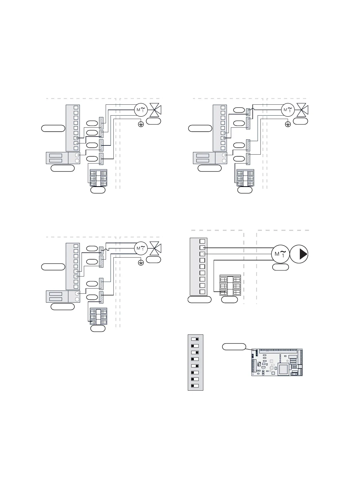
Connection of three-way valve motor (QN14)
Connect the three way valve motor (QN14) to top clip
X21:3 (PE), top clip X22:3 (L), top clip X23:3 (operation)
and top clip X24:3 (N).
1
2
1
2
3
4
5
6
7
8
9
3
2
1
N
L
PE
$$;
$$;
41
;
8QLW ER[ ([WHUQDO
;
;
;
;
&RQWURO
Connection of three-way valve motor (QN15)
Connect the three way valve motor (QN15) to top clip
X21:4 (PE), top clip X22:4 (L), top clip X25:2 (operation)
and top clip X24:4 (N).
1
2
1
2
3
4
5
6
7
8
9
3
2
1
N
L
PE
$$;
$$;
41
;
8QLW ER[ ([WHUQDO
;
;
;
;
&RQWURO
Connection of three-way valve motor (QN16)
Connect the three way valve motor (QN16) to top clip
X21:5 (PE), top clip X22:5 (L), top clip X25:3 (operation)
and top clip X24:5 (N).
1
2
1
2
3
4
5
N
L
PE
6
7
8
9
3
2
1
$$;
$$;
41
;
8QLW ER[ ([WHUQDO
;
;
;
;
&RQWURO
Connection of any circulation pump (GP13)
Connect the circulation pump (GP13) to AA5-X9:8 (230
V), AA5-X9:7 (N) and X1:3 (PE).
1
2
3
4
5
6
7
8
9
L
N
PE
3
2
1
8QLW ER[ ([WHUQDO
*3
$$;
;
DIP switch
The DIP switch on the accessory card must be set as fol-
lows.
ON
12345678
ON
12345678
-X9
-X2
24 20212223 1516171819 1011121314 567891
1
N
L
PE
PE
1
2
3
4
5
6
7
8
2
3
4
5
6
7
8
9
234
-X8
-X4
-X10
-X1
$$6
Relay output for cooling mode indication
It is possible to have an external indication of cooling
mode indication through the relay function via a potential
free variable relay (max 2 A) on terminal block X5.
If cooling mode indication is connected to terminal block
X5 it must be selected in menu 5.4.
AXC 50Chapter 10 | Passive/active cooling (2-pipe)42