CONNECTING EXTERNAL OPERATING
VOLTAGE FOR THE CONTROL SYSTEM
NOTE
Only applies to power connection of 3x400V.
NOTE
Mark up any junction boxes with warnings for
external voltage.
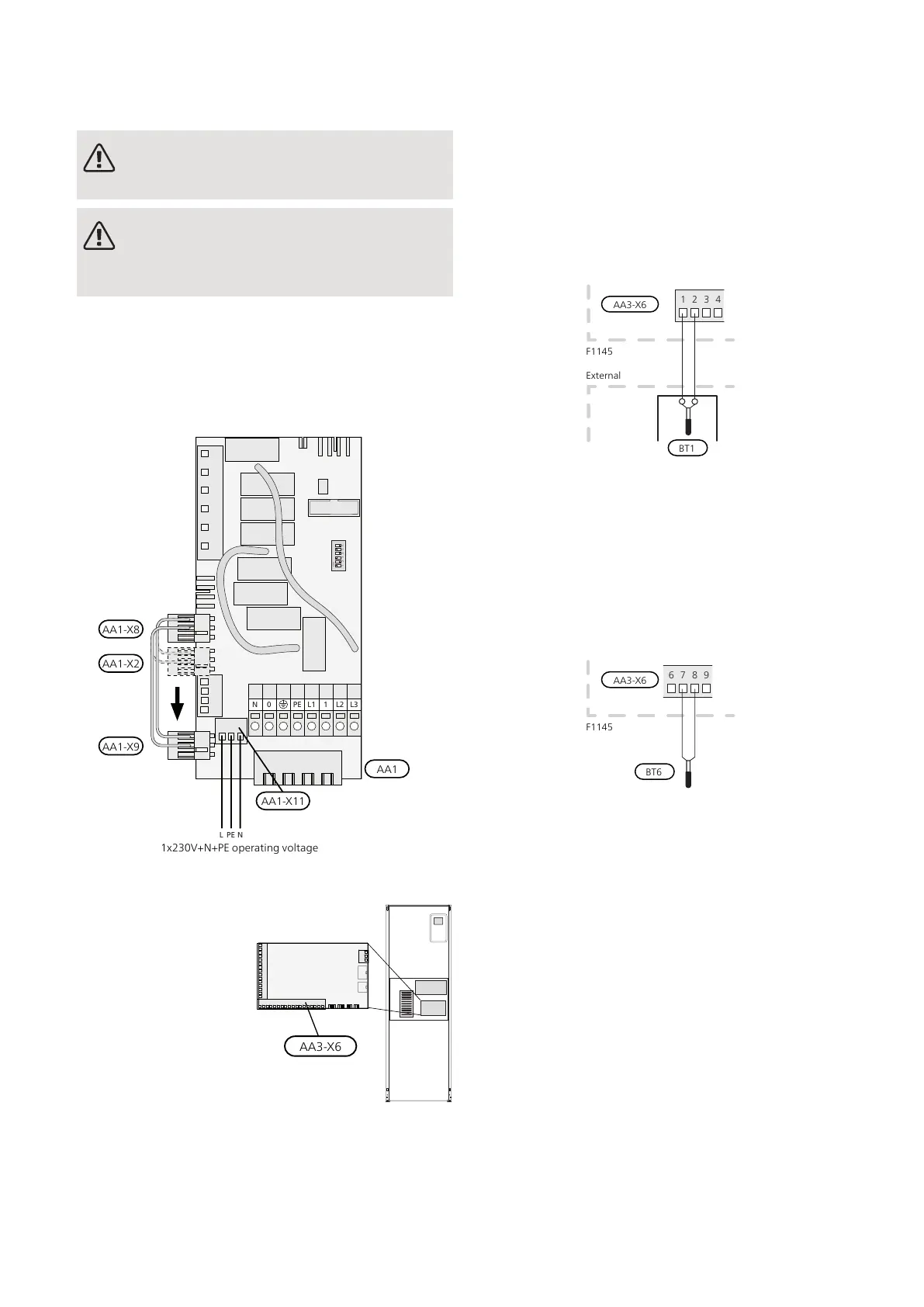
If you wish to connect external operating voltage for the
control system to F1145 on the immersion heater circuit
board (AA1) the edge connector at AA1:X2 must be
moved toAA1:X9 (as illustrated).
Operating voltage (1x230V ~ 50Hz) is connected to
AA1:X11 (as illustrated).
ON
L1 1 L2 L3PE
PE
0N
NL
1x230V+N+PE
1x230V+N+PE operating voltage
AA1
AA1-X8
AA1-X2
AA1-X9
AA1-X11
CONNECTING SENSORS
Connect the sensor(s) to
terminal X6 on input
board(AA3) according to
the instructions below.
Outside sensor
Install the outdoor temperature sensor (BT1) in the
shade on a wall facing north or north-west, so it is unaf-
fected by the morning sun for example.
Connect the sensor to terminal block X6:1 and X6:2 on
the input board (AA3). Use a twin core cable of at least
0.5 mm² cable area.
If a conduit is used it must be sealed to prevent condens-
ation in the sensor capsule.
Temperature sensor, hot water charging
The temperature sensor, hot water charging (BT6) is
placed in the submerged tube on the water heater.
Connect the sensor to terminal block X6:7 and X6:8 on
the input card (AA3). Use a 2 core cable of at least 0.5
mm² cable area.
Hot water charging is activated in menu 5.2 or in the
start guide.
Temperature sensor, hot water top
A temperature sensor for hot water top (BT7) can be
connected to F1145 via soft inputs for showing the
water temperature at the top of the tank.
The temperature sensor, hot water top (BT7) is connec-
ted to the selected input (menu 5.4, see page 27) on
terminal block X6 on the input card (AA3) which is loc-
ated behind the front cover and in a submerged tube on
the water heater.
Use a 2 core cable of at least 0.5 mm2 cable area.
23Chapter 5 | Electrical connectionsNIBE F1145
 Loading...


