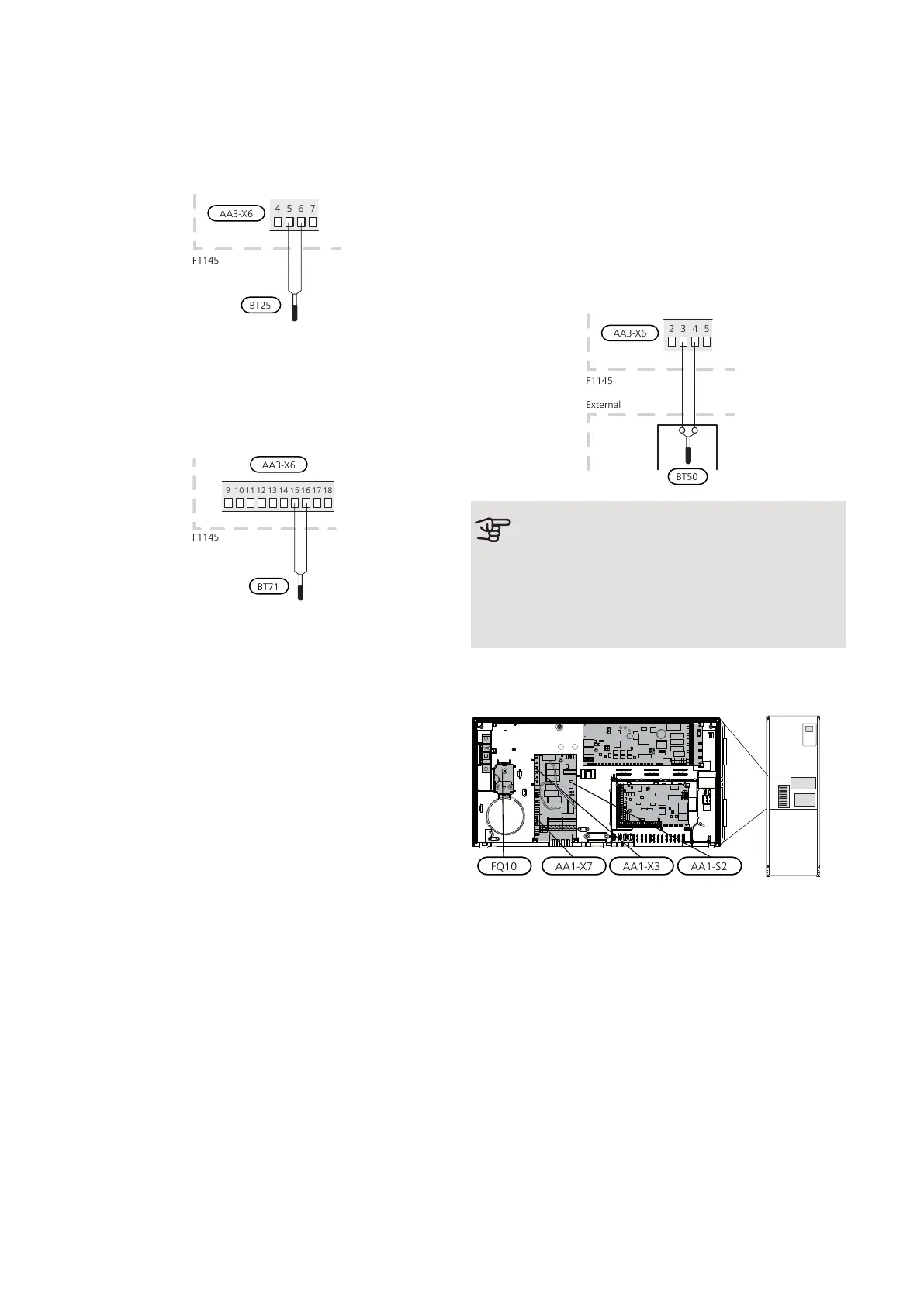
Temperature sensor, external flow line
If temperature sensor, external flow line (BT25) needs
to be used, connect it to terminal block X6:5 and X6:6
on the input card (AA3). Use a 2 core cable of at least
0.5 mm² cable area.
Temperature sensor, external return line
If temperature sensor, external return line (BT71) needs
to be used, connect it to one of the AUX inputs on the
input board (AA3). Use a 2 core cable of at least 0.5 mm²
cable area.
BT71
F1145
189
10 11 12 13 14 15 16 17
Room sensor
F1145 is supplied with a room sensor enclosed (BT50).
The room sensor has a number of functions:
1.
Shows current room temperature in the display on
F1145.
2.
Option of changing the room temperature in °C.
3.
Provides the option of fine-tuning the room temper-
ature.
Install the sensor in a neutral position where the set
temperature is required. A suitable location is on a free
inner wall in a hall approx. 1.5 m above the floor. It is
important that the sensor is not obstructed from meas-
uring the correct room temperature by being located,
for example, in a recess, between shelves, behind a
curtain, above or close to a heat source, in a draft from
an external door or in direct sunlight. Closed radiator
thermostats can also cause problems.
The heat pump operates without the sensor, but if one
wishes to read off the accommodation's indoor temper-
ature in F1145's display, the sensor must be installed.
Connect the room sensor to X6:3 and X6:4 on the input
board (AA3).
If the sensor is to be used to change the room temper-
ature in °C and/or to fine-tune the room temperature,
the sensor must be activated in menu 1.9.4.
If the room sensor is used in a room with underfloor
heating, it should only have an indicatory function, not
control of the room temperature.
Caution
Changes of temperature in accommodation
take time. For example, short time periods in
combination with underfloor heating will not
give a noticeable difference in room temperat-
ure.
Settings
ELECTRICAL ADDITION - MAXIMUM OUTPUT
Number of steps, maximum electrical output and supply
on connection for the immersion heater varies depend-
ing on model. See tables.
The electric additional heat may be restricted depending
on the selected country.
On delivery, the immersion heater is connected for a
maximum of 7 kW (switchable to 9 kW).
Setting max electrical output
Setting maximum output in the electric additional heat
is done in menu 5.1.12.
NIBE F1145Chapter 5 | Electrical connections24
 Loading...


