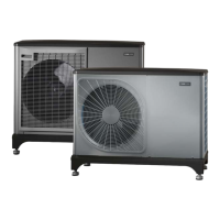
SYSTEM DIAGRAM
System diagram with hot water and a heating system.
The heating medium side and the domestic hot water side
must be fitted with the necessary safety equipment in ac-
cordance with the applicable regulations.
-EB101-QM1
XL1
XL2
-EB101-QM40
-EB101-QZ2
-EB101-FL10
-EB101-RM1
Heating medium connection, supply (from F2050)XL1
Heating medium connection, return (to F2050)XL2
NOTE
Connection of, and other work on, the cooling
system may only be carried out by a qualified
technician with the correct qualifications and the
required certificates.
Symbol key
MeaningSymbol
Shut-off valve
Tapping valve
Non-return valve
Circulation pump
Expansion vessel
Filterball
Pressure gauge
Safety valve
Reversing valve/shunt
Air/water heat pump
Radiator system
Control module
Domestic hot water
Water heater
Pipe coupling heating medium
circuit
You can find a list of compatible products in the section
"Compatible indoor modules (VVM) and control modules
(SMO)".
Caution
There is a difference between connection to a
control module compared with connection to an
indoor module.
See the Installer Manual for the indoor module/con-
trol module.
Vent the heat pump by the "heating medium supply" con-
nection (XL1) using the venting nipple on the enclosed flex-
ible hose.
Install as follows:
• expansion vessel
• pressure gauge
• safety valves
• drain valve
For draining the heat pump during prolonged power fail-
ures.
• non-return valve
Installations with only one heat pump: a non-return valve
is only required in those cases where the placement of
the products in relation to each other can cause self-cir-
culation.
Cascade installations: each heat pump must be fitted with
a non-return valve.
• charge pump
• shut-off valve
To facilitate any future servicing.
• enclosed filterball (QZ2)
Installed before connection "heating medium return" (XL2)
(the lower connection) on the vacuum pump.
• reversing valve.
When connecting to the control module, and if the system
is to be able to work with both the climate system and the
hot water heater.
The image shows connection to the control module.
23Chapter 4 | Pipe connectionsNIBE F2050

 Loading...